Over several years, I have upgraded my fuel system substantially from the stock Ford van system. There were so many problems:
- Stock filter head had a poor filtration rating
- Bleeding the system was a PITA
- The filter head would piss all over your engine and accessories during a filter change
- Stock fuel system was notorious for leaking and air intrusion
- The stock design was bafflingly over-complicated
- The lift-pump-to-filter-head metal line obstructed the best access to the IP
- A lift pump diaphragm failure could result in catastrophic engine damage
- MOST IMPORTANTLY: The stock filter head used up the most valuable real estate in the van engine bay.
I wanted to design a better bleeding system, spruce things up, make things more efficient, and improve filtration. So over the last two years, I’ve been testing and implementing various system options to optimize all the desired characteristics above.
Long Story Short: I installed a 7-9 psi Duralift E-pump and R&D’s Stage 1 dual filter setup on the frame, then ran rubber fuel hose up to a custom fuel supply “hub” which then connects to the R&D IP Inlet elbow.
Detailed Explanation:
Since I wanted to keep the stock fuel tank and sender apparatus intact, along with the stock diesel fuel selector valve, I knew that my custom fuel supply intervention would need to start directly after the selector valve. The lines that connect the metal fuel tubing to the selector valve are plastic, which reside in a sheath of rubber. By cutting the line a few inches in front of the selector valve, I was able to slide on a diesel-rated fuel hose directly around the blue plastic stock line, and preserve the selector valve fittings without some sort of cobbed up fitting.
This is where I wanted to install R&D’s Stage 1 Filter bracket on the frame rail. Justin does a spiffy job of welding up that bracket so it’s a 2-minute install, however, my van just didn’t have the real estate under the van. I have a lot going on down there. Under the van, I have the following additional accessories:
- Gearvendor Unit
- Third Fuel Tank (Biofuel)
- Biofuel Heated Fuel Circuit (FPHE, Heated filter head, Dedicated E-pump, insulation, and various coolant shut-off valves.)
- Coolant Filter
- Rear Heater Core and Air Conditioning Hoses
 All this stuff resides in the space in front of the middle fuel tank, driver’s door, C6 crossmember, and transmission. If I ever wanted to run a front driveshaft, I’d be SOL.
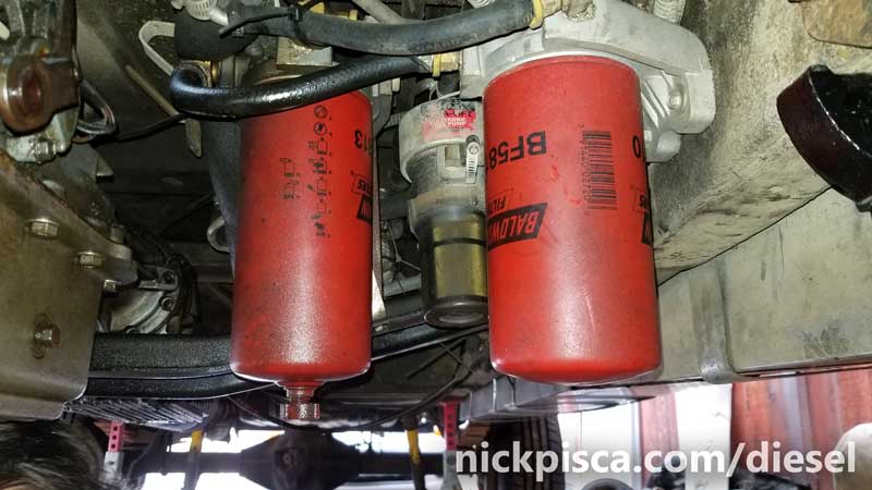
So, installing R&D’s filter bracket was out of the question. I pulled the filter heads off the aluminum mount and found some spots for the e-pump, water-block- and fuel filters on the C6 Crossmember.
I’ll get into the wiring of the E-Pump later.
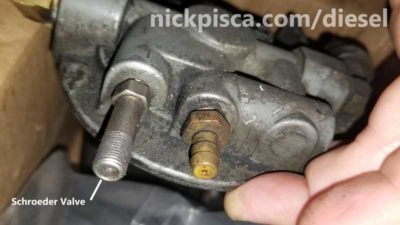 With the e-pump and filters on the crossmember, all I needed to do was run a hose up to the IP. Not really. Without a means for bleeding the air from the fuel lines, it would be almost impossible to start the engine. The stock system has a Schrader Valve on top of the stock filter head, in the image on the right.
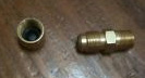 I needed to install my own custom Schrader Valve somewhere at the highest point of the fuel system, to ensure that any bubble that gets trapped in the lines will be expelled when I push the valve. After a decent amount of researching, I found a company that sells “Ford 7.3 Diesel Powerstroke FUEL RATED Viton Schrader valve/adapter” which threads into a standard 1/8″ NPT port.
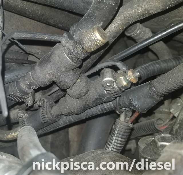
My first attempt to install a bleeder was using a couple aluminum tee’s at the top of the engine bay. It worked ok. In hindsight, it was a poorly located because I had to construct a makeshift tray to collect my diesel as I purged the system. And it almost always dripped down the fuel lines and sprayed on the backside of the Air Conditioning Compressor.
Biofuel Circuit:
Before I move on to the finished bleeder hub design, I need to back up a few steps. I briefly mentioned I have a third biofuel tank and full biofuel circuit in addition to the diesel-side fuel system I’m designing. The reason why they are separate is because the following reasons:
- WVO will polymerize with mild steel, copper, and brass. The vast majority of the stock system exclusively uses these materials.
- Biofuel will eat up conventional rubbers and seals, so viton seal replacement is prudent.
- WVO needs to be heated to 150-180 deg F, so all my biofuel lines and components are heated via the rear heater core circuit.
- WVO needs a different fuel pump to accommodate all the additional fuel lines, oil viscosity, and custom components, and still maintain proper pressure at the IP inlet.
Up to the IP inlet, both my diesel-circuit and biofuel-circuit are completely separate. The biofuel needs to be up to temp in order for it to match the viscosity of diesel, thus making it viable for pumping through the IP and injectors. I start the vehicle on diesel, drive it until the biofuel is heated, then it is ready to “switch over to veg.” I complete this switch over by running an electrical selector valve at the top of the engine, and an additional return line selector valve near the rear of the engine. Basically to simplify this description, I have to warm up the grease to run on it, and I have to purge the oil with diesel before I turn off the engine. The “supply” and “return” selector valves allow me to accomplish this.
My selector valves are controlled by two switches on the dash. The second switch turns on the “return” selector valve. That one is pretty easy. The first switch is more complicated. When I turn that on, it powers up the “supply” selector valve, the biofuel e-pump, and lastly, it runs an NC relay that kills the power to the diesel-side e-pump. It doesn’t make any sense to be running the diesel e-pump while I’m driving on grease.
The Selector, Sensor, and Bleeder Hub:
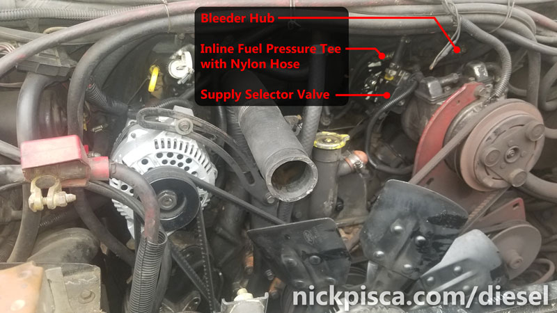
I installed the “supply” selector valve and bleeder hub behind the compressor. Also, while I was diagnosing an unrelated fuel pressure issue, I installed a nylon hose mechanical fuel pressure gauge, with a simple NPT tee on the fuel hose going to the IP. Also, the bleeder tee had a temp sensor on it, because when I’m running on grease, I want a gauge in the van to tell me I’m getting proper fuel temperature into the IP. If it’s too cold, it can cause injector damage. If it’s too hot, it can affect timing and other components.
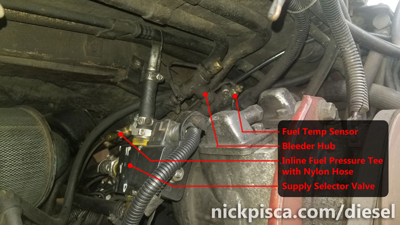
Since I was still exploring how I wanted to finalize and polish this layout, I just zip-tied this stuff together to get a feel for the design. It was a Rube Goldberg setup. I never liked it and it needed to be improved, big time.
 Improvements:
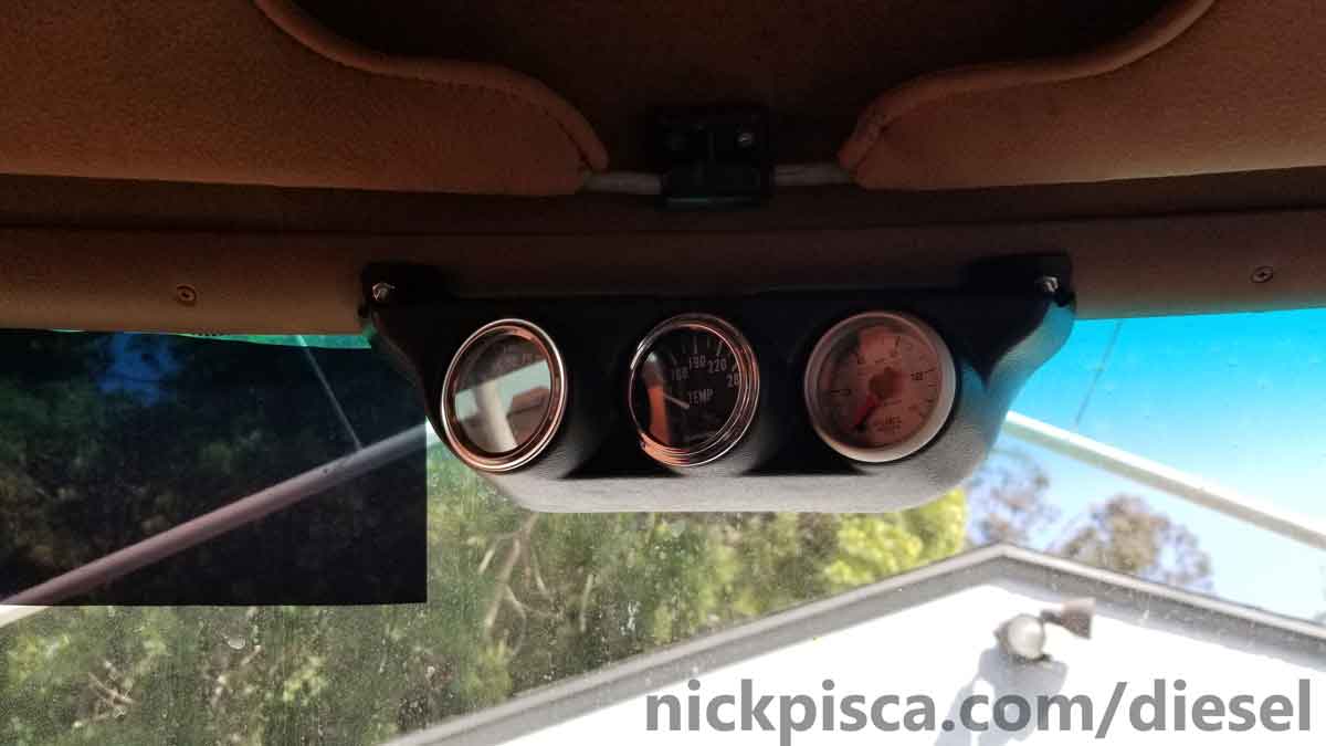
Recently, I installed some new gauges, rebuilt the engine and swapped them. While I had the empty engine bay, I thought it was time to do this fuel system overhaul. One of the new gauges included a spiffy (and expensive) Autometer electronic pressure gauge. This was a far superior design than the mechanical nylon tube, that had a pin-hole leak due to vibration or something, and it dribbled diesel on the top of the engine. I always hated those nylon tubes, so I’ve upgraded all my gauges to electronic senders.
For the “new” Bleeder Hub, wanted all the components to mate in one glorious assembly. The following items fit into the hub:
- Electronic Fuel Pressure Sender (for the interior gauge)
- Mechanical Gauge (for seeing the pressure from the engine bay)
- Electronic Temp Sensor
- Selector Valve Outlet
- Bleeder
Also, I want the bleeder to extend into the accessible area of the engine, so I can cleanly bleed the air without spraying fuel everywhere. Using some aluminum 4-way tee’s, aluminum 1/8″ NPT hose bibs, and some aluminum tubing (aluminum doesn’t react with biofuel), I constructed what I think is the most efficient way to coalesce all these components, and mount them to the underside of the engine bay:
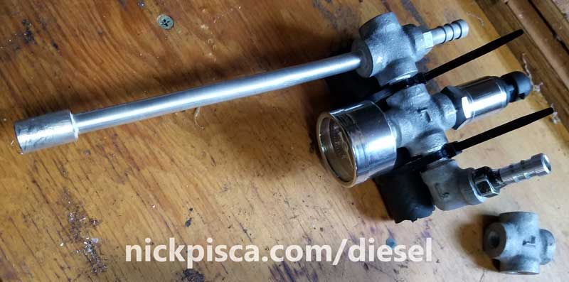
This hub has some rubber stoppers on the top to prevent any metal rubbing on the engine bay or coolant lines. They are fastened to the underside of the bay ceiling near the top of the compressor. The bleeder extends into the front of the engine, and it really works nice.

The hose on the left connects to the “supply” selector valve. That outlet pushes the fuel to the 90 degree elbow, which feeds into the 4-way housing both fuel pressure sensors/gauges, which feeds into the second 4-way that extends the bleeder and houses the temp sensor. Then a final outlet bib connects to a hose that connects to the IP inlet elbow.
This design uses less volume than the previous design, and it implements even more components than before.
Overall:
The new design has worked really well. It’s nice seeing the fuel pressure while I’m working on the beast. Also, the bleeder works perfectly. The only improvement I made to the bleeder was to put a small section of rubber hose so it was a little more flexible to manipulate the Schrader Valve. The temp and fuel pressure sensors have functioned as design, allowing me to get accurate readings while running on biofuel or diesel.
At some point I’ll upgrade this post to include more information on the details of the biofuel circuit.
No warranty. You are responsible for your vehicle. For novelty use only. Not responsible for anything or anyone. Not responsible for damage to your vehicle, you, or anyone or anything.
Copyright 2000-2018 Nick Pisca 0001D LLC