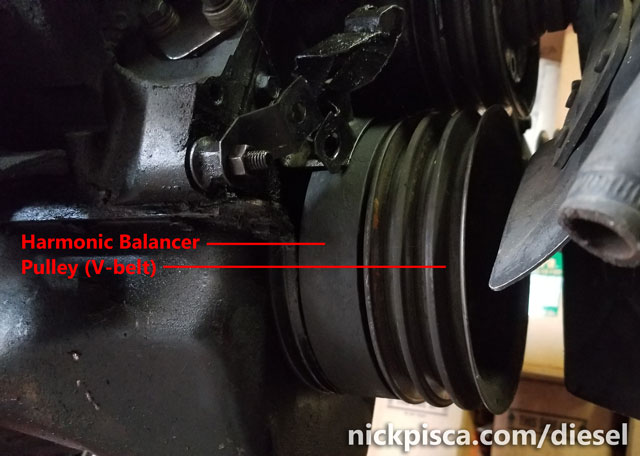
The harmonic balancer, also known as the “vibration damper,” sits on the front end of the crankshaft. It is press fitted on the shaft with a small steel woodruff key to orient the direction. If a person needs to service the crankshaft, remove the front engine plate, replace the front main seal, or do other internal repairs on their IDI engine, the harmonic balancer may need to be removed. Also, if the harmonic balance has damage, it may affect engine timing and may need replacement. This procedure will require special tools that can usually be rented for free at any auto parts store. The following article entails my process for removing the balancer.
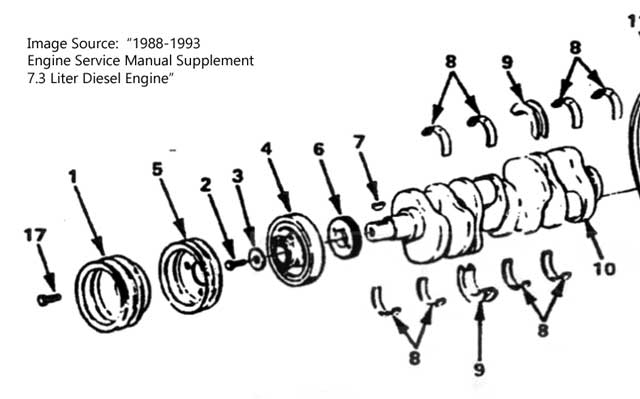
There are several components fastened to the front of the harmonic balancer that need to be removed. Using the diagram above, here are the names:
- Generator Drive Pulley (for the v-belt version, not for serpentine belts)
- Hex Head Bolt (15/16″)
- Crankshaft Washer
- Vibration Damper (Harmonic Balancer)
- Crankshaft Pulley (for the v-belt version, not for serpentine belts)
The front pulley assembly has four retaining bolts and a retaining disc (not photographed). I needed to remove these four bolts (that reach down through the harmonic balancer) before I could extract the balancer from the crankshaft drive. NOTE: the center crankshaft bolt (15/16″) does not need to be removed to get the pulley off.
Sometimes the bolts are rusted on or torqued on so tight that trying to undo them will turn the engine cycle. Since I had the engine on the stand, I just jammed a 3/8″ drive extension in the flywheel/flexplate to stop the spin. If the engine was in the vehicle, a couple v-belts looped around the pulley held by a friend should be enough to keep the engine from cycling.
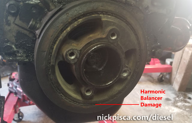
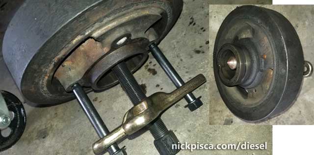
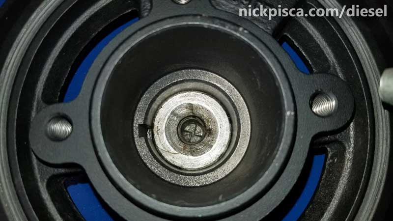
Once the pulley was removed, the rubber layer showed obvious wear and tear. This balancer will need to be replaced or have the sleeve repaired.
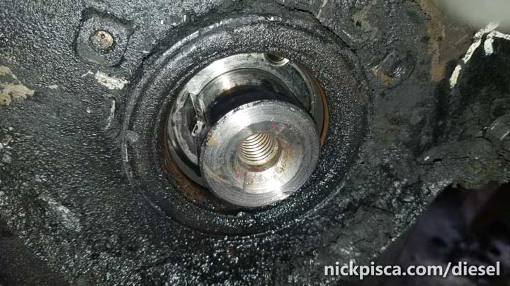
Before the Harmonic Balancer Puller can be used, the main crankshaft bolt must be removed. Again, if turning the bolt turns the engine, use one of the aforementioned methods to constrict the rotation.


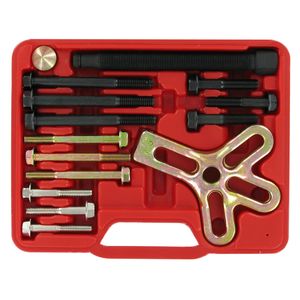
The next process required a special tool, a harmonic balancer puller. It is basically a set of high-strength bolts, a compression cap, and puller flange. The largest bolt threads into the center threads of the puller flange. Then the kit should have some bolts that screw into two opposing balancer threads.
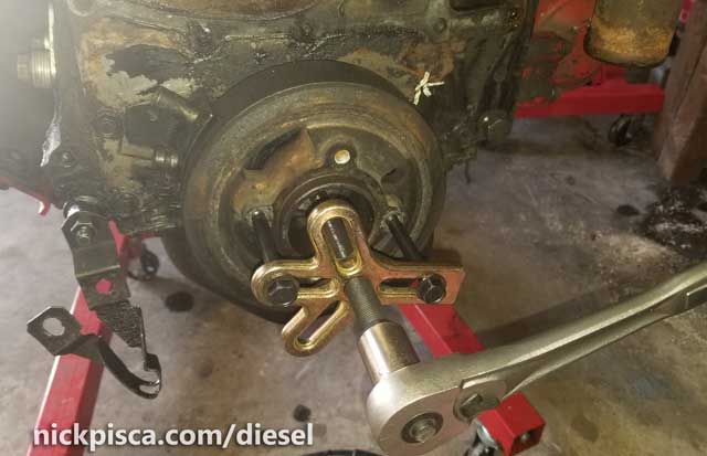
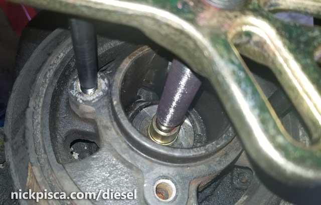
The compression cap should be inserted on the end of the big bolt; it distributes the compression load on the crankshaft equally so it doesn’t damage the shaft. Also, it is imperative that the tool be liberally greased on the main bolt threads and compression cap, so that they can spin without binding. In the image below, you can see the reddish-purple grease coating my puller threads and inside the compression cap.
The tool is pretty simple. I threaded on the secondary bolts as far as they can go. If I didn’t get enough threads, it might strip the threads out when I pull it out. Also, the secondary bolts need to be exactly the same length so that the puller is parallel to the face of the harmonic balancer. Using a socket wrench, turn the larger bolt and compression nut until it situates in the center of the crankshaft hole. Then using the socket wrench, continue to turn the center shaft until it starts pulling the balancer off the shaft.
Eventually it will start sliding off the crankshaft.
Reinstallation:
While I had the Harmonic Balancer off, it was a good time to do the front and rear seals, which is detailed here. With any new seal, it is prudent to lubricate the pliable parts with engine oil (with expected immediate use) or assembly lube (for storage) prior to the compression of the balancer on the front of the crankshaft. We don’t want a dry surface to have undo wear and tear in the first break-in of the engine.
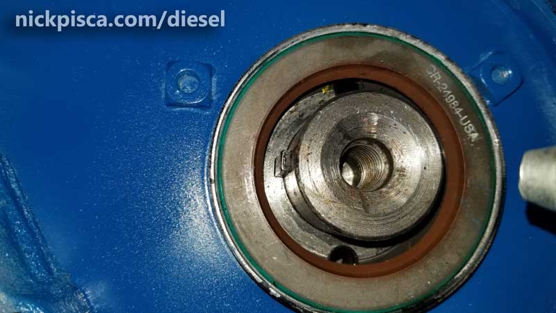
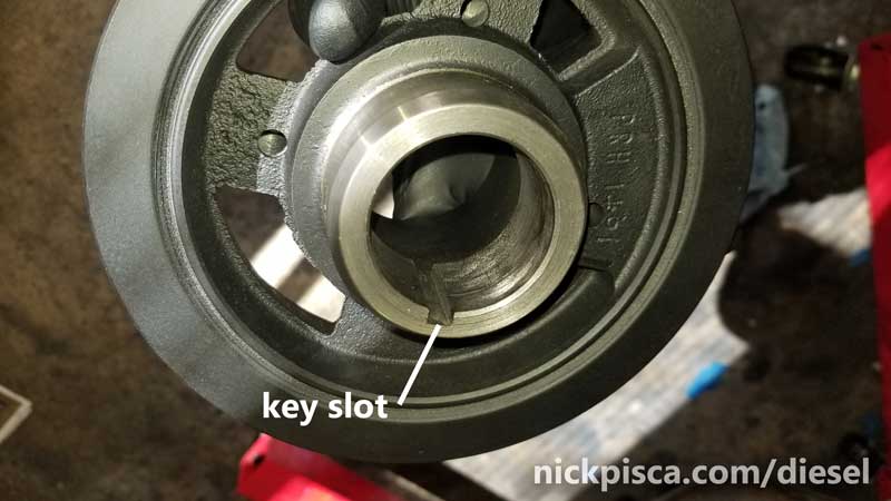
The crankshaft will need to be lightly permatexed along the perimeter of the shaft mating surface with the balancer. This will prevent any leakage through the small area between the crank and balancer, which may seem unlikely, but still a potential area for seepage. Also, the crank has a “key” which MUST LINE UP with the “key” slot on the balancer. Without the key and slot, the balancer would not 1.) balance (surprise, surprise), and 2.) give the proper timing measurement.
So I applied a thin layer of permatex, I applied a thin coat of engine oil to the front seal, I cleaned off the harmonic balancer surface so the sealant can make a solid seal, and slid it on the crank making sure to line up the key with the slot.
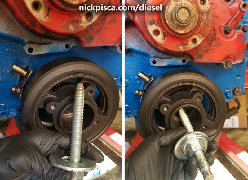
Since the surfaces are nearly exactly the same size down to the thousandths of an inch, it will NOT slide on far. The rest of the installation must be accomplished with a 5/8″ thread bolt and nut. It will compress the balancer down the shaft without damaging the engine. While it might seem tempting to pound on the balancer with a mallet or hammer to push it on, this would be a no-no. It will just cause extreme damage to the crank instead. The best course of action is obtaining a 6″ long 5/8″ diameter bolt and nut, like this:
I was unsure about the thread type on the inside of the crank, so I brought my 15/16″ bolt from the crank with me to the hardware store to match up. It is pretty hard to find this specific item at a typical Home Depot or hardware store, so if you are planning on doing this in the future, you might want to order a Grade Eight 5/8″ fully threaded bolt in advance from McMaster. The nuts and washers (an assortment of 5/8″ up to 1″ diameter interior hole washers were used) are easy enough to obtain at any decent store, but it is imperative to obtain Grade Eight washers. Standard washers will bend and warp with almost no resistance, and even my high strength washer bent a little under the load of the compression.
I threaded the 5/8″ bolt as far in as it would go into the crankshaft. The more threads I could use, the better it would hold up trying to compress the balancer on the shaft. If your threads are dirty, make sure the chase them to clean them out prior to doing this. If your threads are messed up, I don’t know what to say… the crank might be irreparably damaged.
Using a wrench, I gradually torqued down the nut, which gradually forced the balancer down the crankshaft. With each compression, I cautiously checked to make sure it align PERFECTLY. If it torques on eccentrically, it will damage the balancer. If at any point I felt it was going on wrong, I used the balancer puller to remove it and try again.
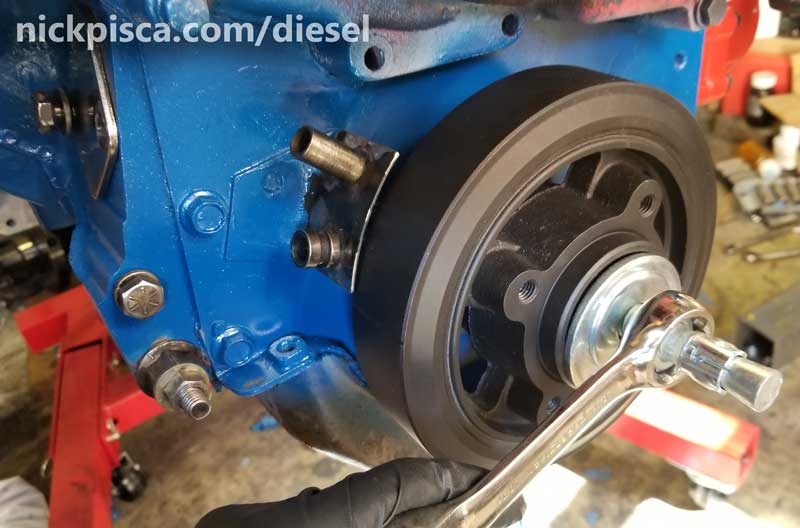
Eventually, it slid all the way on. (Side note, in the images above, I was using a low grade steel 5/8″ diameter bolt. While I was torquing it on, the threads on the bolt eventually gave way, and the nut just spun in place. Thankfully, the balancer and the crank were never in any danger of damage, but the bolt and nut were shot. I didn’t take a picture of that failure, partially because I was already annoyed with the hours of searching stores for a fully threaded bolt. It was another setback, so I wasn’t in the mood to capture the bolt failure. Eventually I did find a Grade 8 bolt so I could finish the job. It takes a LOT of force to push this balancer on this shaft, so a Grade 8 is the only thing that will resist the pressures required.)
It should be about an 1/8″ from the oil pan edges. Any closer, and it might clash with the pan when the engine spins. Any further, and it might not line up with the pulleys on the water pump and elsewhere. Once the balancer is in the proper position, I reinstalled the 15/16″ front crankshaft bolt and thick washer to retain the balancer. The shop manual recommends it to be torqued down to 90 ft-lbs.
Finishing Touches.
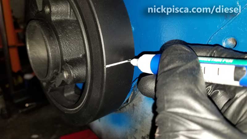
When I put my harmonic balancer back on, using a white-out pen, I drew a line in the timing groove. Why paint the line white? Once the engine is reassembled and started, you have to time the engine. A bright white line shows up really well with a timing gun strobe light. I’ve found that the metal-tipped white-out pens are the best, because they fit perfectly in the balancer groove. It allows the paint to coat the bottom of the groove. If you use a standard white-out pen (without a metal tip) or a white-out brush, it will likely not make a clean line like the metal ones do.
No warranty. You are responsible for your vehicle. For novelty use only. Not responsible for anything or anyone. Not responsible for damage to your vehicle, you, or anyone or anything.
Copyright 2000-2018 Nick Pisca 0001D LLC