After I finished the Rod and Piston Ring work, it was time to toss on the cylinder heads and tighten the ARP head studs. If you followed my previous blog about the time I put on my heads and studs with the engine in the van, then you know doing this on the engine stand will be a lot easier.
While tearing down the engine for the crank job, I decided to use the ’94 IDI block with the ’88 replacement heads from the last HG job. The heads were newly cast and dressed. From the aforementioned article:
- “EMS of Inglewood called to say the heads were warped in the middle, out of spec for thickness, couldn’t be resurfaced without exceeding the min spec, and the springs were on the bottom of spec strength. After some searching around, we called Diesel Cast Welding to build us a new set of heads, completely dressed. They arrived in about a week or so.”
Since these heads only have about ten thousand miles on them, they are basically new, and I know the seals and specs are in good condition. Plus, cleaning off the mating surfaces will be a lot easier on new metal than the old surfaces.
In this article, I’m not going to detail the teardown process. Perhaps a future article can be a dedicated “teardown” thread.” Instead, this article will focus on the preparation and installation of heads, head gaskets (HG), and ARP head studs on a 7.3 IDI.
Cleaning and Preparation:
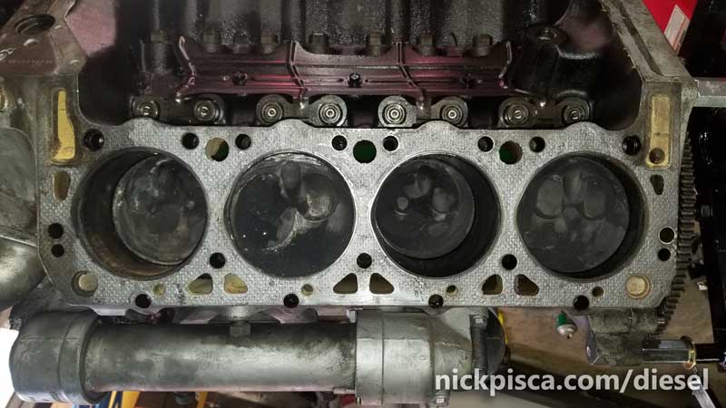
Probably the most important part of a HG job is making sure the deck is thoroughly clean. Unlike a typical t-stat gasket or fuel pump gasket job which uses paper gaskets and/or permatex, HG’s are made from metal and other rigid materials that are not very forgiving. An improperly cleaned surface will always lead to coolant, oil, or both leaks. Worse yet, it could lead to combustion gas leaks, and worst, oil-in-coolant, coolant-in-oil, or combustion pressure entering coolant system.
I pulled off the heads and this mess was the condition of the block deck.
 While there are plenty of goofy videos of guys scraping off HG’s with sanding discs and metal scrapers. I don’t do that. Way too risky. Instead, I use a plastic scraper with some gasket remover to painstakingly scrape the HG remnants from the block. It really is an awful process. Using an abrasive brush or pad (like a brillo pad) will scrape grooves or depressions into the block surface, and basically ruin it. So, the day of scraping begins.
While chatting with the guys at EMS, they once recommended using a large razor blade. I was shocked, but then they explained that in no way was the blade to be carving away at the gasket. Instead, the blade would be placed perpendicular to the deck surface and lightly scratch the deck, always keeping the blade perfectly perpendicular. I never engaged with this technique, for I was always afraid I’d end up scratching surface. The blade could quite easily carve a groove in the deck.
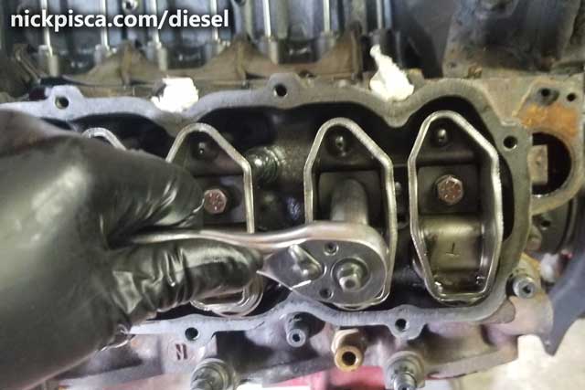
Also, the Cylinder Heads need to be cleaned up as well. These were new, but also were used on a block for a few months. I pulled them off and lucky for me, the new HG didn’t attach to the head deck very much.
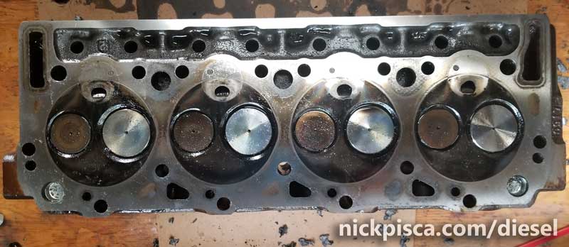
With a little brake cleaner and other cleansers, the heads were ready for primetime. Also, because I wanted to paint this and the block later, I attacked the sides of the head with some light rust remover. Since we were in such a hurry to toss these heads on in the previous head job, I never got to paint them. This time, I want to clean them up all around so it can get the royal treatment.
Lastly, the most important part of cleaning up the block for new ARP head studs is CHASING the threads. For the 6.9, the studs are 7/16″ and for the 7.3, the studs are 1/2″. Since there are not many thread chasers that go deep enough for this process, I had to make my own. Using a 4″ Grade 8 bolt, I ground out a couple grooves with an electric grinder. The importance of extremely clean threads will become apparent later in the article. Also, some guys wrongly use a tap and die set to clean their threads. I think this is dangerous, because a jumped thread could result in the total destruction of the torque capacity of those threads.
 Installing the Studs and Head Gaskets:
I got my set of ARP studs from R&D IDI Performance. He had the best deal and by far the best service in the cottage industry that is the IDI repair world. Studs are threaded in with an allen wrench, even though their instructions call for “hand tight.” I use ARP Assembly lubricant, which if you don’t know, lubricates the threads so that a perfect torque can be performed. Dirty threads can result in a premature torque resistance.
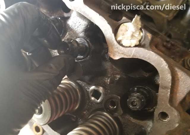
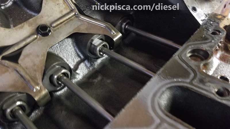
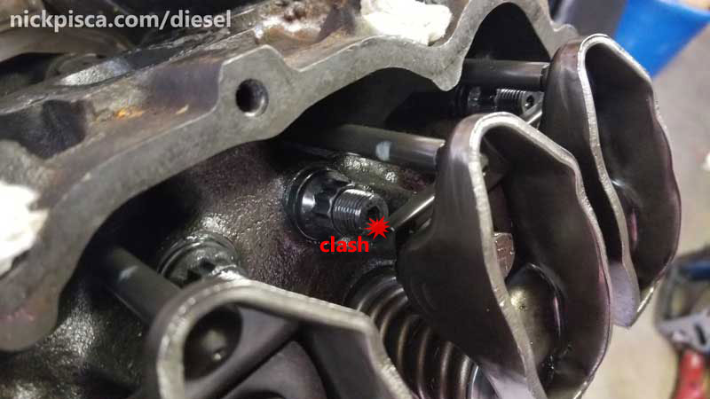 It is crucial that these studs be threaded in as far as they can go. This is why the threads must be chased. Why so deep? The natural assumption is to ensure enough threads to torque down the heads, but honestly, my reasoning is because the dimensions are so tight, that an extra 1/8″ up would conflict with the rocker arm retainers on the heads (see image to the right). It’s kind of a poor design, because there really is no room for error. And let’s say you put them in and they are too long? Then you have to pull the stud with the head in place, chase the thread again, then reinstall the stud and try again. And that can get tedious.
Before the studs go in, be sure to find some 7.3 IDI head pegs, to align everything properly. They reside in the top right-most and left-most stud holes.
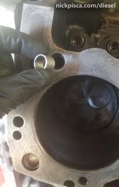
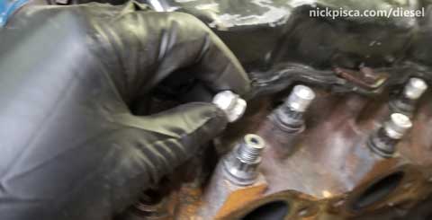
With the threads chased, I put in the studs. Just in case it isn’t obvious, head studs have threads on both ends. The courser threads enter the block, and the finer threads protrude out for the end-nuts. The nuts are installed later, after the head is slid over the studs to meet the block surface.
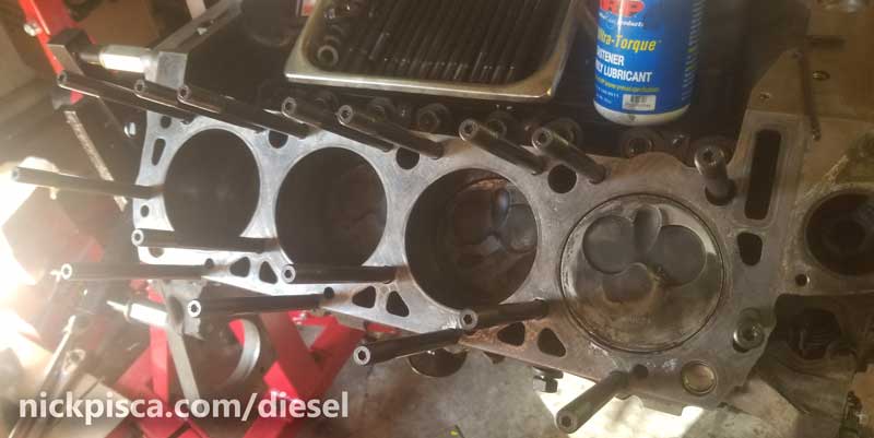
With the studs in place, I carefully slid on the HG.
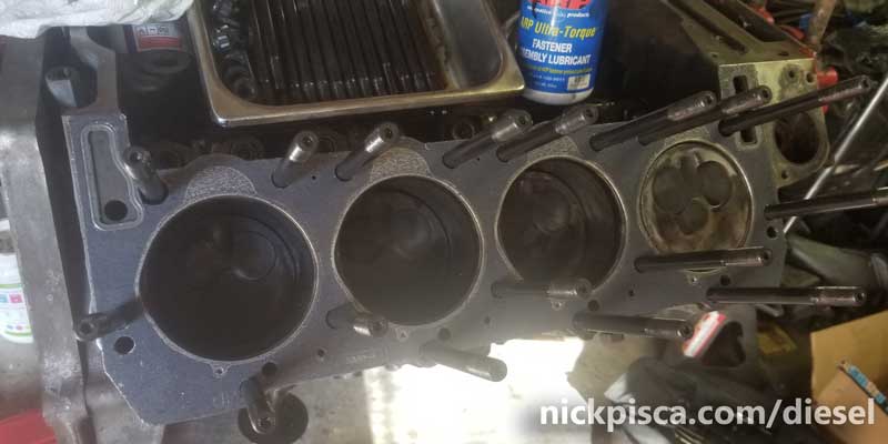
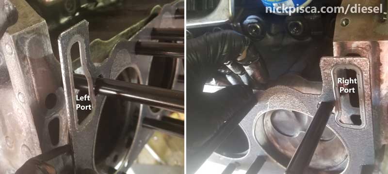
When placing the HG, make sure the coolant ports match up with their respective sides.
Installing the Cylinder Head on the Block.
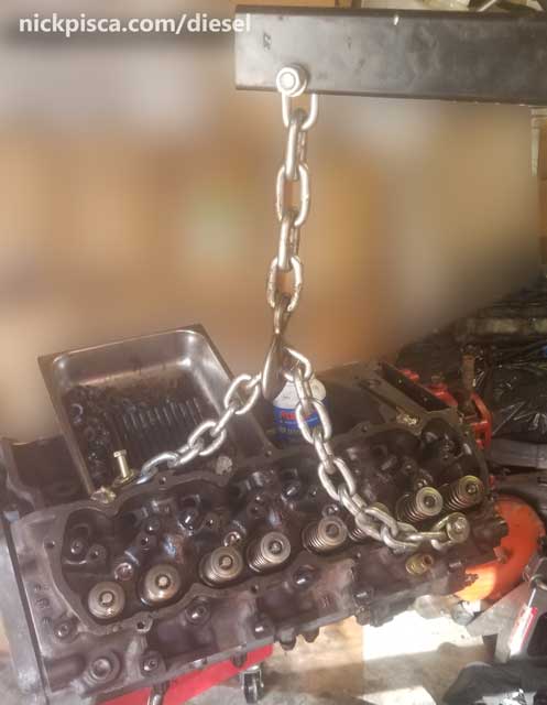
I’m usually doing all my repairs on my own. This means I have to be really creative with my tools and crane. These heads are about a hundred pounds fully dressed, so lifting these on my own and lined them up with protruding studs would be almost impossible on my own, and one slipped stud into the deck of the head could result in an enormous scratch. So to hedge my bets, I hung my head from my shop crane with a lot of chain slack. This way I can dangle the head from the crane, adjust the crane height to the elevation of the midpoint of the studs, and then gently lift (with my arms) the heads over the studs. Then when I relax the heads, I can use the shop crane to gradually bring the cylinder head down to the HG.
Using some ARP Lube, I dabbed each ARP washer and ARP nut and threaded them on each stud. They have a tighter thread that allows for extreme torque and compression pressure resistance. These got hand threaded as far as they go, because the torque sequence is a lot more elaborate than other typical projects.
7.3 IDI Cylinder Head Torque Specs and Sequencing.
Once all the nuts were hand tightened down, the convoluted torque sequence can begin. Since the torque spec exceeds 3 digits, it might be prudent to create a secondary support mechanism, just in case you tip over your engine on a stand. If you are doing this in the vehicle, best of luck to you. I did it in a van, you should be able to do it in a truck much easier, but getting 100-some ft-lbs while teetering over a fender is going to fun. And exhausting. You’ll break a sweat for sure.
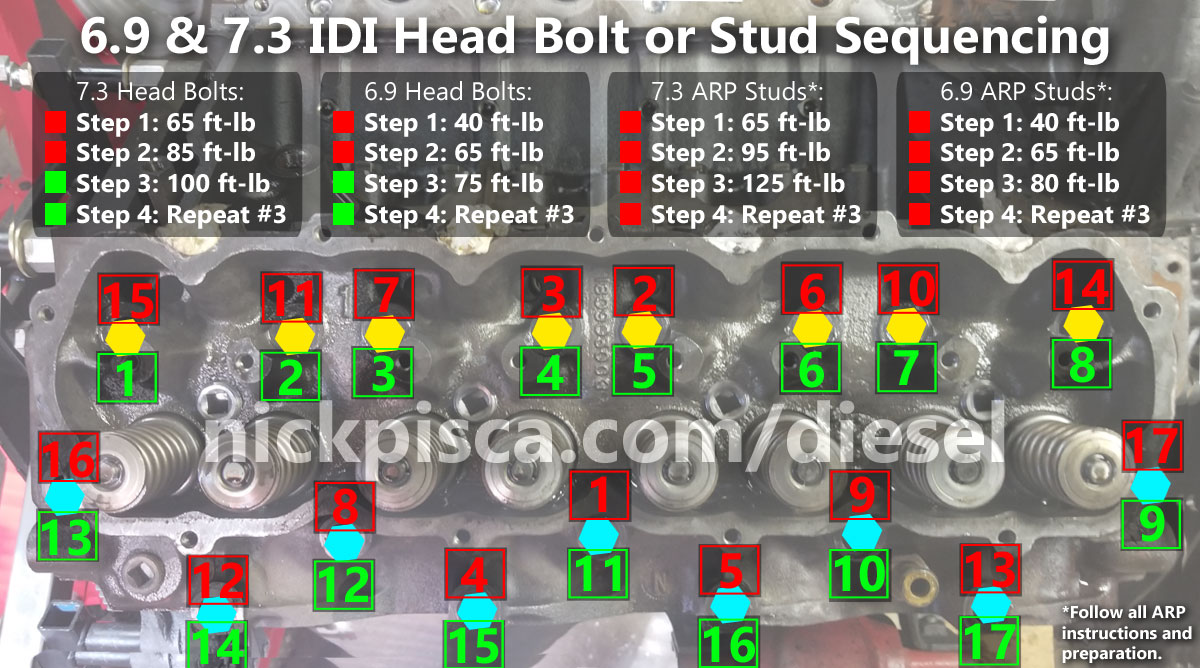
7.3 IDI Head Bolt Torque and Sequencing
In the diagram above, I have the recommended IH head bolt spec and sequence. The red numbers denote the first and second rounds of torques, and the green numbers denote the third and fourth rounds. The yellow tags denote ARP nuts that are housed inside of the valve cover, while the blue tags show external ARP nuts.
The spec in the image is for stock head bolts. ARP head studs can hold A LOT more torque than that. So my sequence was 1st: 65 ftlbs, 2nd: 90 ftlbs, 3rd: 115 ftlbs, 4th 140 ftlbs, 5th same as #4. In my previous head job, I did the finish torque at 150 ftlbs (which R&D IDI Performance recommends), but considering my torque wrench only went up to 140, I didn’t trust the max capacity of my wrench giving a proper limitation. Also, there are other specs for head bolts, like when I installed the Hypermax Turbo on my van. Hypermax recommends:
- “To reduce the possibility of cylinder head gasket leakage, it is advisable to re-torque the cylinder head bolts to (6.9L-85 Ft./Lbs. 7.3L-110 Ft./Lbs.) after 3,000 miles has been accumulated on the vehicle”
Back to the project at hand, the yellow hex tags (in the image diagram above) are crucial that the stud reached as far into the block as possible, because they are susceptible to clashing with the rocker arm retainer if they are installed too high. The blue ones need some kind of protection from the engine gunk, so I install these spiffy aluminum aeronautical caps that thread on. They keep the gunk out of the external threads and hex slot, and look pretty tits.
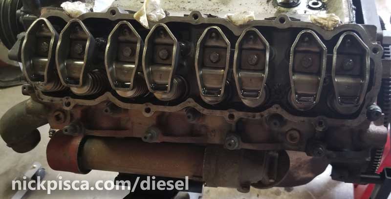
Next step, I slid in the push rods. This is pretty trivial, and when disassembling the engine in the first place, makes sure to label all push rods and rockers so they can be reinstalled. Since my heads are newly being installed on this block, it really doesn’t matter.
The rocker arms bolt on next. I have the later style rockers. They need to torqued to around 20 ft-lbs.
If at any point (as stated previously in this article), the rocker arm retainers clash with the ARP studs, then you are SOL. I had a few do this on the previous job, so this time, I made sure that all threads were vigorously chased to limit this possibility. For a visual on the clash, see the image to the right.
Badabing…
Accessories, Ports, Sensors, etc:
Since this blog is specific to the IDI Van (but not limited to), I thought I’d touch up on the placement of the plugs and ports.
- The coolant switch sensor is located on the front-top of the passenger-side cylinder head.
- The heater core hose exit port is located in the middle threaded hole on the passenger side of the passenger-side head.
- The driver’s side cylinder head has no ports used for stock components. These threaded ports would make excellent candidates for an aftermarket coolant temp sensor, since the Ford stock sensor is dumb AF.
No warranty. You are responsible for your vehicle. For novelty use only. Not responsible for anything or anyone. Not responsible for damage to your vehicle, you, or anyone or anything.
Copyright 2000-2018 Nick Pisca 0001D LLC