A while back, I got a spare 7.3 IDI engine out of a 1994 U-haul van. It was a really good deal, because the PO had a shop pull the engine, determine the problem, and get a repair estimate. The problem for him, the estimate was in the thousands of dollars. He needed the van, engine, and tranny gone ASAP, so he sold the pieces for whatever he could get, because the shop didn’t have space for his oversized paperweight.
I bought the engine without knowing the origin of the problem. All the mechanics told me was the 7th piston was delayed when he turned the flexplate. I got the beast home, along with various other IDI parts (always be scavenging!), and put the block on a spare engine stand. I needed a decent block, because my original 1988 7.3 IDI had some kind of crack in the block that was pushing oil in the coolant. My plan was to combine all the “good” parts from both engines and make one rebuilt IDI for the van.
Investigation:
Eventually, I got a moment to extract the oil pan and investigate the source. Here’s a video of the clunking:
As you can see from the video, the rod bearing on the left-side journal is clearly failing. But how bad? I pulled off the rod caps to check it out.
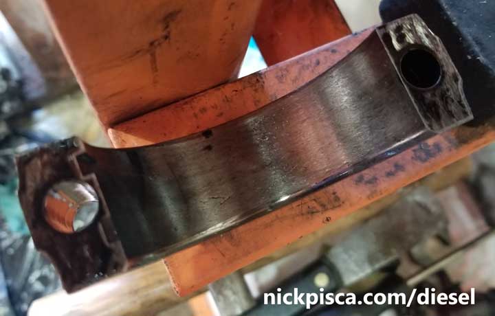
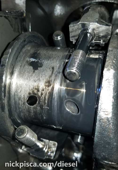
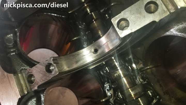
Immediately pulling the rod cap off, I realize there is a major issue. As far as I could tell, there was NO bearing in the cavity. Also, the rod cap is scratched to hell, and this is supposed to be a smooth surface. I turn my attention to the crankshaft journal:
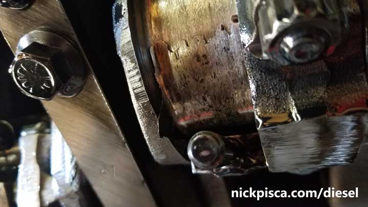
OUCH! Not only is the crankshaft journal totally scratched up, but there appears to be a worn-down bearing wedged in the cavity that looks paper-thin. I had to pull the other rod cap on the same journal because it was so deformed, it curve into the space between the rods.
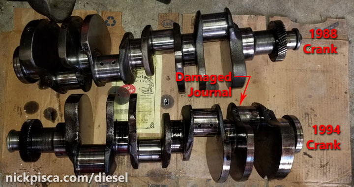
When you compare the two rod caps and compare the two sides of the crank journal, you’ll see this is a bad situation. If you look close enough, you can visibly see a depression on the worn side of the journal. This basically means the crankshaft is garbage, because even though the crank can be reground in 0.010 inch increments, this is far beyond the standard grinding specifications.
Comparison:
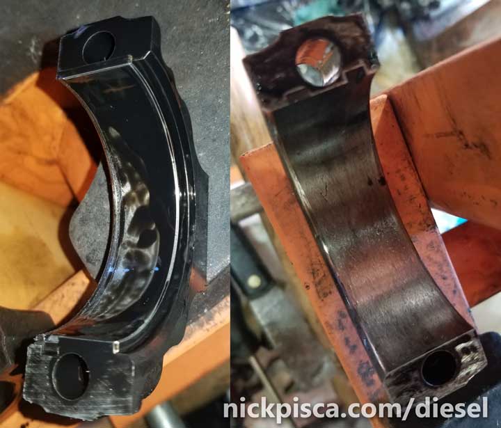
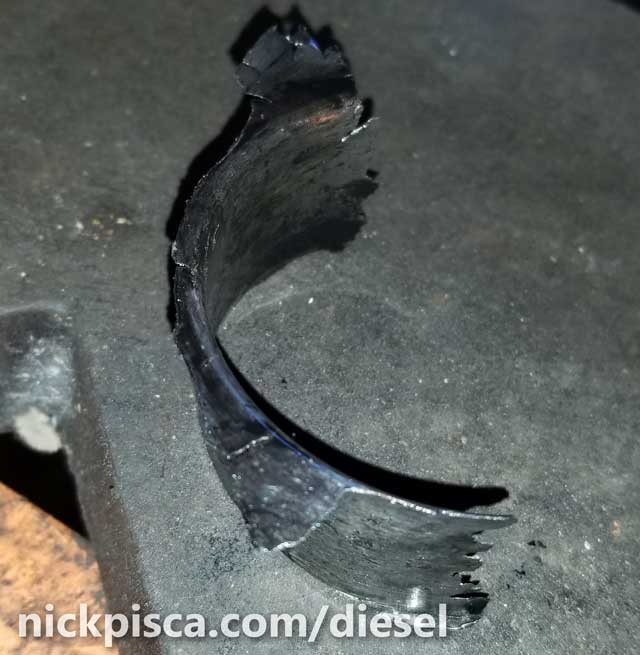
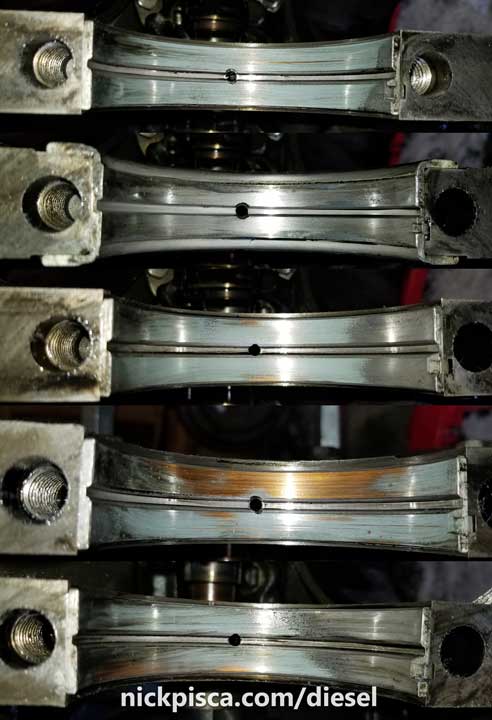
In the image above, the left picture shows a healthy bearing and rod cap. For the 7.3 IDI, the caps bearings are approximately an eighth of an inch thick. On the right, the bearing has completely worn down to nothing. In the image below, the left side was the worn bearing. On the right side of the journal, you can see proper oil lubrication and a smooth journal finish.
Tear down.
Since the crankshaft is totally shot, I’m going to continue with my plan to use this block and combine the best parts from both 7.3 engines. If I have to pull the crank out of this block, that means I need to undo all the crank bearing caps, rods, and remove all the pistons. Basically, aside from undoing the camshaft and it’s components, I’m stripping this down to the block.
NOTE: The PO’s mechanics has already removed the heads, valley pan, harmonic balancer, and other components. It was just a block (without heads), with the flywheel (for the E4OD), oil pan, oil pump, and cam components. I won’t be detailing how to remove these components in this article, but I will have a separate article showing how to remove and install the harmonic balancer, and another detailing the teardown process of the 1988 7.3 IDI van engine.
First I undid the flexplate (a flywheel for an auto transmission) for the E40D tranny from the 1994 7.3. It is mounted directly to the rear of the crankshaft with 8 bolts. There 9 holes (one hole is used to line up the flexplate).
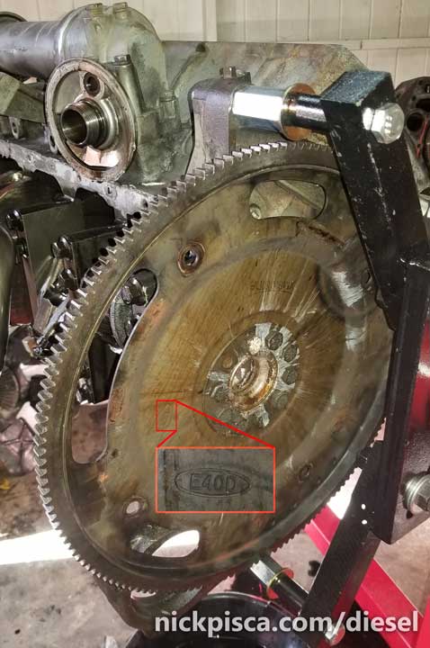
Unlike the harmonic balancer, I didn’t need a special puller to remove the flexplate. Just slid a 3/8″ drive long extension in one of the torque converter access holes, and unscrewed the bolts with a pry bar. However, behind the E4OD flexplate, there is a half-inch thick spacer between the plate and the crankshaft. (NOTE: the C6 transmission has a different space and flexplate, which will be detailed in a future post on this site.) It is solidly attached to the crankshaft, so at first, I was convinced it was one solid piece combined with the crank. However, with some wiggling and tapping with a rubber mallet, I was able to wiggle off the spacer from the crankshaft.

Once the E4OD flexplate and spacer is removed, I can remove the rod bearing caps, rods, and pistons from the chambers. One by one, I remove the rod caps, and carefully take note of each rod and rod cap label. Just in case you do not know, each rod and rod cap has its respective label on one side of the rod. These components are married, and caution should be taken to make sure these parts are not mixed with other pieces.
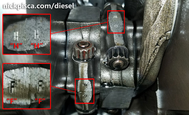
Unscrew the 12-point nuts retaining the rod caps in place. There should be a thin washer installed with these. If not, then whoever rebuilt this engine didn’t properly secure the rod caps. The cap will likely not just “come apart.” They fit snuggly with the bolts on the rod (they taper to “receive” the cap holes), and it takes a bit of work to finagle them apart. Resist the urge to wedge a straight edge or blade in between the members, because you might inadvertently damage the rod bolts.
Once both caps are uninstalled, you should be able to push the pistons out of the top of the block. If you haven’t removed your cylinder heads yet, you might want to bone up on my other post discussing that here. You will need to remove your heads if you want to pull the rods out. If you are confident that your pistons and rings are in good condition, then you should be able to push the pistons up to the top of the cylinder and keep the rod bolts out of the way of your crankshaft. A trick I learned on the net to protect your crankshaft from incidental scratching from the rod bolts is to slide on some fuel hose sections on the threads. I am not convinced my piston rings are in good condition (contrary to the confidence of the PO), so I removed my pistons and rings and inspected them with the proper measuring equipment. That won’t be included in this article, but it is detailed in this dedicated post:
7.3 IDI Piston Ring Gap Measurement, Custom Grinding, and Proper Installation
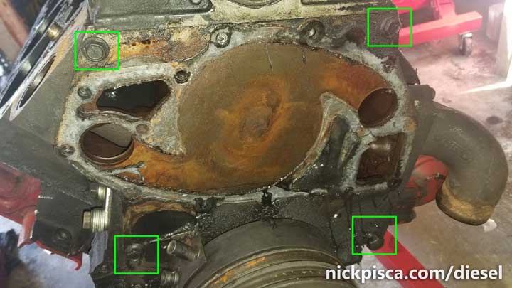
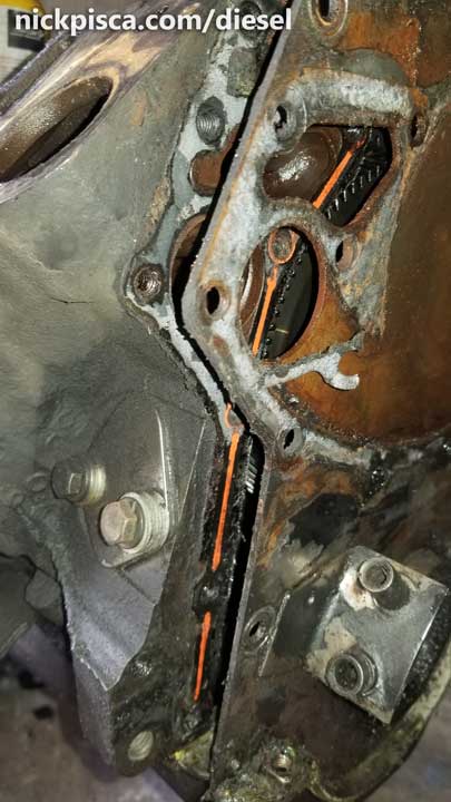
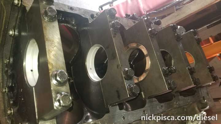
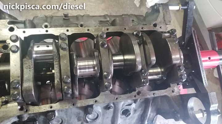
Once the pistons and rods are removed, I have the room to undo the crankshaft bearing caps and bolts, to extract the crankshaft. In the image below, I have highlighted in red the identifier numbers for each of the crank main bearing caps. The 7.3 IDI has 5 main bearing caps, and all of them are numbered in order from 1 to 5 from the front to the rear of the engine. There is a chevron adjacent to each number to help the mechanic properly orient his/her main caps to the front of the engine.
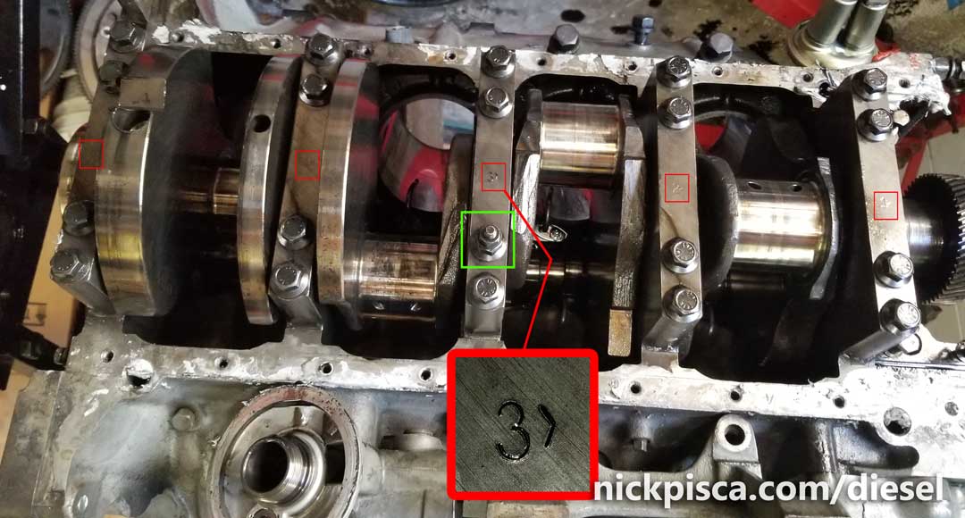
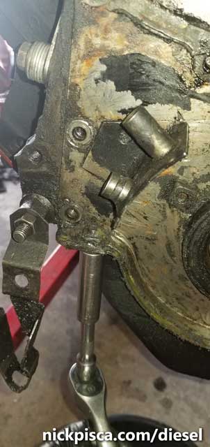
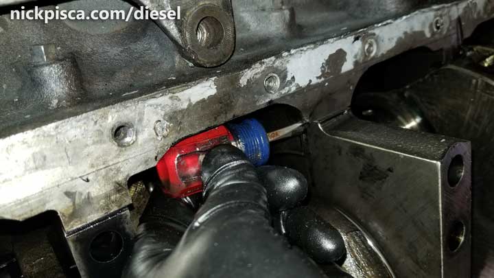 I have also highlighted (in green) the oil pump nozzle retention stud located on the #3 Main Bearing Cap. Make sure to note this location for future use so it can reinstalled in the proper position. It can be difficult to extract the bearing caps because they wedge into the block. I used a small screwdriver (image to the right) at the ends of the caps, where there is a notch that allows a bit of prying action to be performed.
Below, my bearings are clearing overly worn. This usually happens when the bearing sizes were installed incorrectly. Bearings that are too small lead to a larger gap and the oil pressure is not great enough to reach all the proper lubrication surfaces. Bearings that are too large squeeze down on the crankshaft journals, and don’t allow any oil to lubricate the proper surfaces. My bet is the PO didn’t measure the journals properly and put in “Standard” size bearings where “0.010” undersize should have been in place.
 The #3 Main Bearing cap has an odd shaped bearing. It has two semi-circular flanges that wrap the sides of the main cap. These are called Thrust Bearings (image to the right) that resist the front-to-back movement of the crankshaft from the action of the torque converter and transmission. When reinstalling this thrust bearing, you need to use feeler gauges to ensure there is a small clearance between the crankshaft counterweights and the #3 main cap thrust bearing.
 Also, on the main bearings, the bearings in the cap are called the “Lower” bearings and the bearings in the block are called the “Upper” bearings. Upper Bearings have a hole and channel to allow for crankcase oil to flow from the galleys through the hole and into the channel to lubricate the crankshaft journal while the engine is running. It is imperative that recognizing this difference is crucial for allowing engine oil to reach proper areas.
Ordering Replacement Bearings
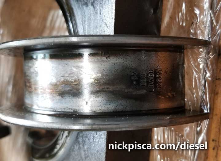
Something I wish someone had told me when I first started doing this type of work was: Check the back of the bearings to get the size you need to order. When I was researching how to measure and install new crankshaft bearings, most tutorials showed how to check your existing or newly-installed bearings for the proper clearances. But, they never talk about how do you buy the correct size bearings to start the job! So once you pull the bearings from your caps and block, mark them so you know where they came from, and then read the back of the metal. There should be impressed text telling you important information:
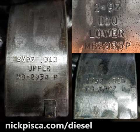 Most bearings have the date they were manufactured, the size (to be explained below), its “upper” and “lower” configuration designation, and its part number. Also, they have a key that allows you to orient the bearing in the proper direction in the cavity. Since it takes time to order and deliver these bearings, the moment you take the bearings out of the block, you should look at the “size” on the back and order a set of Main Bearings and Rod Bearings ASAP.
Bearings come in incremental size: “Standard,” “0.010,” “0.020,” and “0.030” inches undersize. In short, if the crankshaft journal is smaller (undersize), you need a thicker bearing to make up the space. When crankshafts are balanced, the shop will measure the journals to verify if they conform to spec. You can measure this too, if you have an outside micrometer set. According to the Ford Service Manual in the 7.3 IDI supplemental, here are the journal specification limitations.
Main Bearing Journal Diameter
- Standard Size: 3.1228″-3.1236″
- 0.010″ Undersize: 3.1128″-3.1136″
- 0.020″ Undersize: 3.1028″-3.1036″
- 0.030″ Undersize: 3.0928″-3.0936″
Connecting Rod Journal Diameter
- Standard Size: 2.498″-2.499″
- 0.010 Undersize: 2.488″-2.489″
- 0.020 Undersize: 2.478″-2.479″
- 0.030 Undersize: 2.468″-2.469″
If your journal size is worn in between these increments, a machine shop will be needed to grind the journals to the next smaller undersize dimension. Then, the bearings will need to make up that hundredth of an inch.
 While you are waiting for your bearings to arrive, you should pull the crankshaft and get it balanced at a machine shop. But to get it out, the front and rear engine plates should be removed and while they are off, it is a GREAT time to put in new front and rear main seals. The seals on the IDI are notorious for leaking, and while there are some instructions on how to reseal them with the engine still in the vehicle, it is extremely difficult to pull off.
The front and rear engine plates are rather simple to remove. They are held on by small bolts and basic gaskets. Front Plate, bolts in green (in the image above).
I carefully pulled back the plate from the block and pan (if still installed). It comes apart pretty easy if you have the oil pan already removed, but if the pan is still installed, it can really stick to it. Also MAKE SURE to remove the two bolts that thru-bolt through the oil pan and front and rear plates. See the image to the right for one of the locations of the oil-pan-front-plate thru-bolts.
The same process goes for the rear plate as well. Here is a detailed article on how I detached, replaced the seals, and reattached the front and rear plates:
I pulled the crankshafts and compared them. Turns out the 1988 and 1994 7.3 IDI cranks are the same. Yippie.
Installing the New Bearings.
I’m not going to go into the process of measuring the clearances. There are lots of great videos on youtube that explain how to do this. I’m more or less just going to focus on my experiences with the 7.3 IDI engine bearings. My new bearings finally arrived (0.010 size), and I installed them right away. I need to measure to make sure these are the right size for the journals, and if not, reorder a different size or have the crank ground down to a lesser size.
A brief summary of the process is this:
- Install the bearings and caps
- Torque them to spec
- Measure the journal with a micrometer
- Use that measurement to set the Bore Gauge
- Measure the Bore deviation
- Compare against the spec.
I didn’t use any assembly lube while installing the bearings for the measurement. It was imperative to clean all the surfaces of oil and lint so that the measurements can be perfect. I’m measuring down to the thousandths of an inch, so a hair or goop of oil will definitely ruin the calculation.
When installing the bearings, make sure to put the UPPER in the block side and the LOWER bearing in the cap side. I was working my block on a stand with the engine upside-down, so the upper was on the bottom and the lower was on the top, but you get the point. Also, I made sure to match up the notch in the block with the key in the bearing. This keeps the bearing from sliding out of the space laterally. And most importantly, I ensured that my oil holes matched up. IF I didn’t match that up, the crankshaft wouldn’t be lubricated at all, and the engine would be junk within seconds.
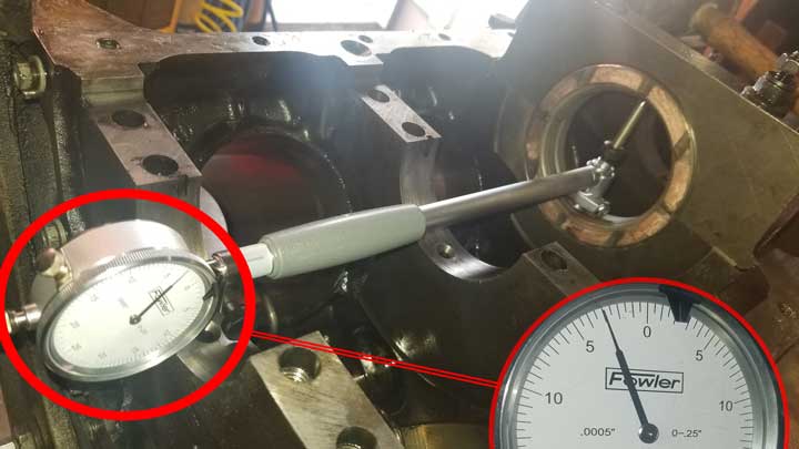
I installed the #3 main cap with bearings and torqued them to the spec. According to the Ford Service Manual, the Main bolts need to be torqued to 95lb-fts, but a side note specified “Tighten four main bearing cap bolts to 75 lb-ft. (102 N-m) before final torque is applied.” Then, the spec says the Main Bearing gap needs to 0.0018′-0.0046″ and the Rod Bearing gap needs to be 0.0011″-0.0036″.
Measuring the bore (in the X and Y directions), it was just at the bottom limit of the specification window.
I torqued down the rest of the caps and checked their measurements.
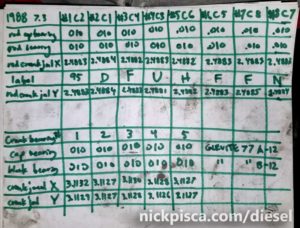 I’ll post the calculations chart I made of all the main bearing bores.
Once all the calculations are complete, I measured again against the journal diameters with my micrometer and double checked that my gaps were within spec. After all that, I removed the bearing caps (AGAIN) and lubed the bearings with clean engine oil. They say if the engine is going to sit for a long time, then use general assembly lube to preserve the engine, but for engines intended to be run immediately, use the oil you plan to use in the engine to lube it. After lubing the surfaces, I carefully installed the 1988 7.3 Crank in the 1994 7.3 block. It all fit together according to the spec and still turned after the dual torque process.
Rods and Pistons
The rod, piston, ring, and cylinder head work required many follow-up articles. I felt including them in this post would make it unduly long.
For more info, visit these pages:
and
7.3 IDI Piston Ring Gap Measurement, Custom Grinding, and Proper Installation
and
7.3 IDI Cylinder Head, Head Gasket, and ARP Stud Installation
No warranty. You are responsible for your vehicle. For novelty use only. Not responsible for anything or anyone. Not responsible for damage to your vehicle, you, or anyone or anything.
Copyright 2000-2018 Nick Pisca 0001D LLC