
Installations
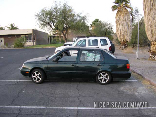 1998 VW Jetta TDI VO Conversion Installation Thread
Dual Tank System
WVO & SVO Compatible
Design and Installation: Nick Pisca, Copyright July 2007-2019
Disclaimer: We are not responsible for anything you do or anyone does to your engine, vehicle, yourself, or others and any property as a result of your modifications. You are responsible for your actions.
WVO Conversion Schematics 98 Jetta Secondary VO Tank Design
COMPONENTS
- 2 twenty-plate heat exchangers
- 1 filter head (fits B2-HPG Baldwin filter, or compatible)
- 1 custom under-mount aluminum tank (10.5 gallon capacity)
- 2 hydraforce fuel switch-over valves
- 1 17-19 inch HotFox fuel pick-up
- 1 4-7 psi fuel pump
- 75 ft 3/8” dia fuel hose
- 10 ft 3/8” dia high pressure fuel hose
- 20 ft 5/8” dia coolant hosing
- 2 12V/30A switches
- 4 30A fuse holders
- various amperage fuses
- 1 temperature gauge
- 25 ft 14 gauge wire
- 10 ft 10 gauge wire
- 1 spool 14-16 gauge aluminum uninsulated wire
- box butt splices, assorted electrical connectors
- box 7/16” head bolts w/ nuts
- box 1/4” washers
- 1 roll reflectix insulation
- 100 pack zip ties
- several brass fittings 5/8” and 3/8”
- many hose clamps
TOOLS
- Safety Glasses
- 3/8” Drive Socket Set (Metric and Standard)
- Phillips + Standard Screwdrivers
- Power Drill
- Drill Bit Set
- 2½ – 3” Hole Saw
- Brake line Pipe-Bender
- 200+ Grit Sandpaper
- Reciprocating Saw or Hacksaw
- Soldering Kit
- Vice-Grips, Pliers, Channel-Locks
- Wire Cutters
- Utility Scissors
- 2-ton Hydraulic Jack
- Jack Stands
- Automotive Manual and/or Service Guide
NOTE: Research Before Converting Your Car!
I’ll assume that you’ve already done your homework on the differences between WVO, SVO, Biodiesel and so on. If not, you probably shouldn’t be following this thread. Some of the basics are…
- WVO = Waste Vegetable Oil
- SVO = Straight Vegetable Oil
- Biodiesel = Vegetable Oil with additives
Rules:
- Your car must have a Diesel engine.
- Don’t pour untreated Vegetable Oil into your Diesel Tank.
If you didn’t know those things already, visit the many forums and websites devoted to VO conversion.
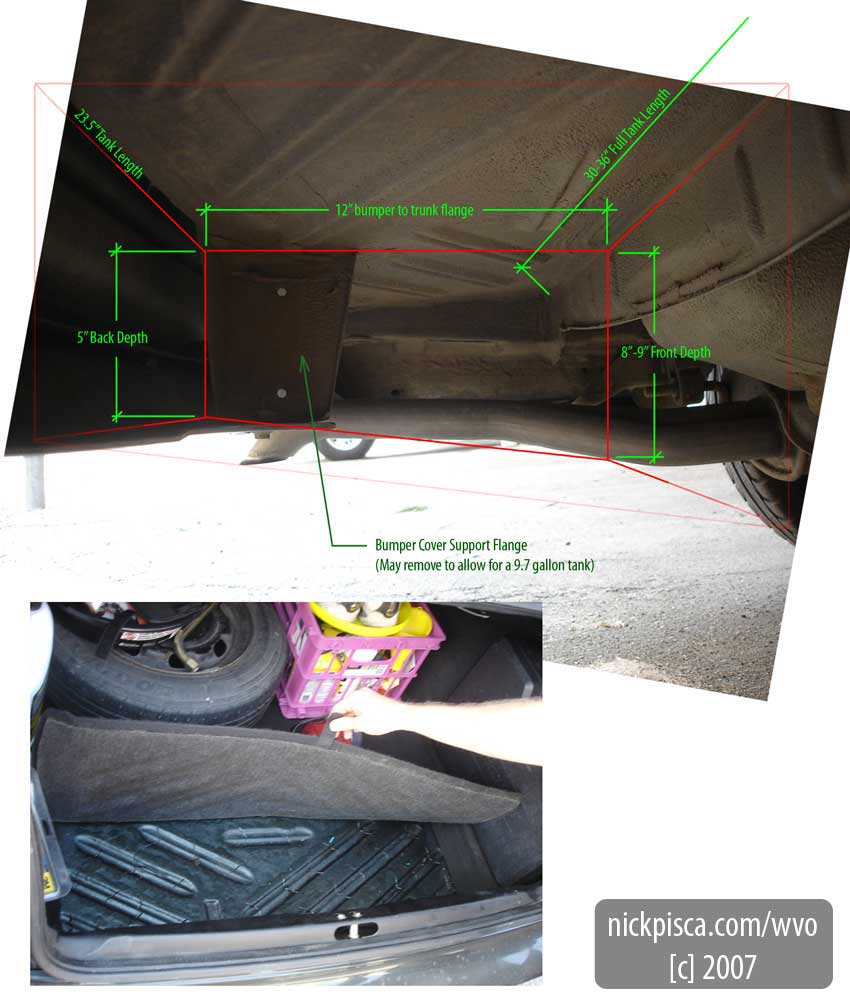
Prior to Installation:
I spent a good deal of time under the Jetta before the conversion looking to for extra spaces. Since the VW is rather small, I wanted to maximize my trunk space by mounting the secondary veggie tank underneath. Luckily, there is a large open rectangular compartment directly under the trunk. After some quick measurements, I speculated that a 12” x 23” x 5” volume could work unobstructed, and a 12” x 32” x 5” tank would work, but require some demolition.
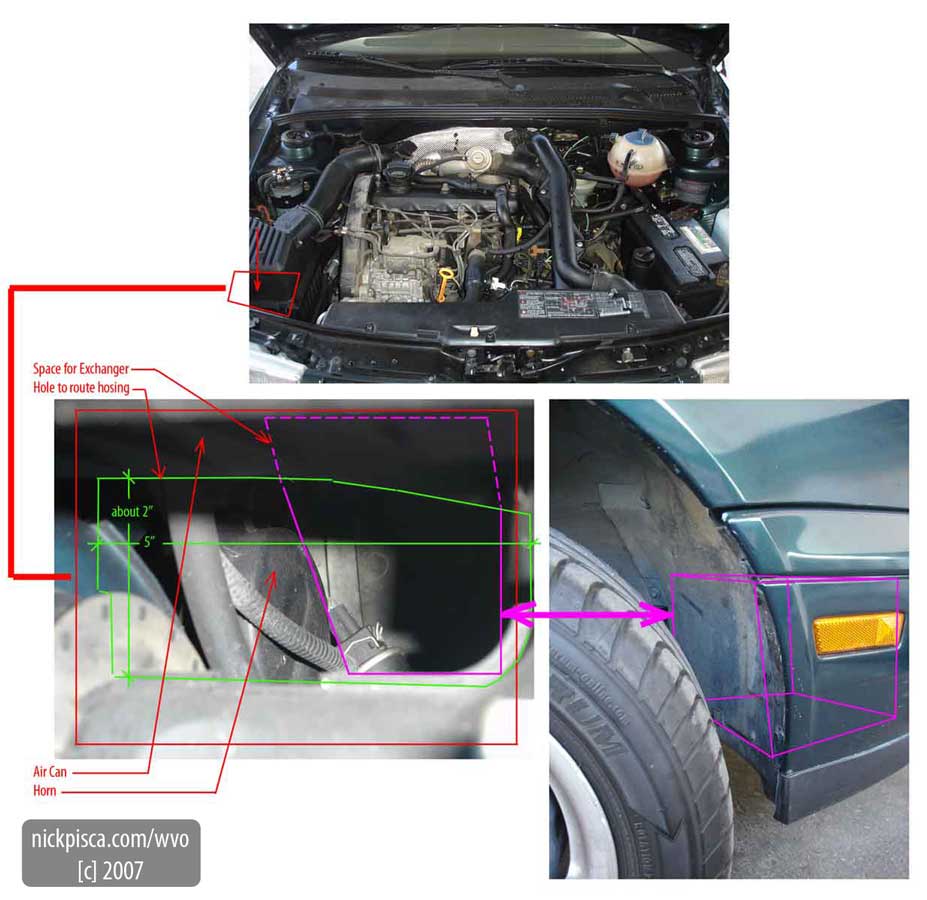
Also, I found some space in the front clip to store the 20-plate Heat Exchanger. I wanted to avoid storing this in the engine compartment, just in case I needed to perform repairs. This component could be in the way.
Near the air conditioning unit, there is a void surrounded by plastic. I didn’t have the heat exchanger yet and hadn’t seen a picture of it, but I suspected that its size would be smaller than the designed space.
After massive preparation, I laid out a strategy to convert the Jetta. This design was the initial plan and did change a little.
Glenn suggested that I move the filter head after the pump, for if the filter clogged, I could burn out my pump. And since I was using a cheapie fuel pump, it will be weak and susceptible to damage. Also, we had a back and forth discussion about whether to have a series or parallel circuit spliced into the heater core. Glenn made a parallel system in his Benz and continued this on his Passat, which was under construction coeval mine. He set up manual valves so he can shut off portions of the coolant circuit if necessary. I stuck with a series circuit because Jeff tried the same thing on his Jetta.
Components – Purchasing and Accumulation
I wanted to make the conversion myself and avoid buying a kit from Frybrid, Golden Systems or PlantDrive. This required finding all the components on my own. Since Glenn was building his Passat too, we tried to buy elements in bulk to save money.
- (2) Hotfoxes – I found a ebay store selling 17-19 inch Arctic Fox Hotfox units for 175 dollars. I offered 300 for two and he accepted it. This was a good deal considering buying them new is over two-hundred a piece.
- (6) 20-Plate Heat Exchangers – Glenn found a Canadian dealer selling nickel-plated exchangers for a reduced rate. We purchased six, but they arrived rather late (due to international shipping). We split them three each, with the anticipation of using two per car. Glenn later installed all three and has been maintaining solid temp.
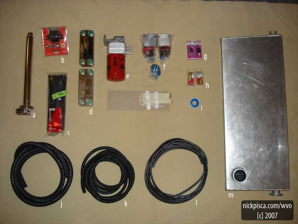
Unit Key:
- A: 17-19 inch HotFox $150
- B: 4-7 PSI Fuel Pump $39.99
- C: 100-pack Zip Ties $3.99
- D: (2) 20-plate Nickel-plated Heat Exchangers $89.90 ea.
- E: Filter Head $110.00
- F: (2) Hydraforce Selector Valves with gasket fittings $99.90 ea.
- G: (2) 30A Automotive Switches $5.99 ea.
- H: Various Brass Fittings
- I: Teflon Tape $1.99
- J: 20 feet 5/8” Heater Hose $13.21
- K: 50 feet 3/8” Fuel Hose $45.98
- L: 25 feet 5/32” Vacuum Line $17.80
- M: Custom Aluminum tank $365.00
- Unmarked: Injector Line Heaters (not used in Jetta conversion) $48.00
- Totals $1187.54
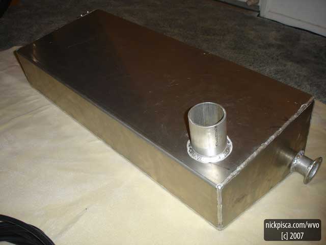
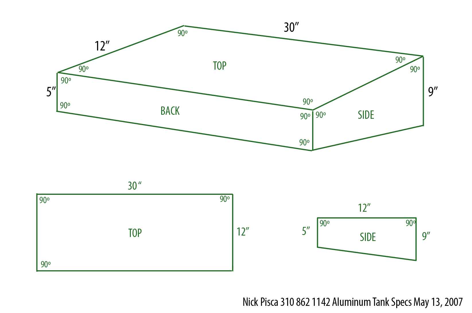
TANK:
The tank design is rather unique and provides the maximum efficiency of unused space in the 1998 Jetta. I wanted my conversion to be very clean and have minimal impact on my engine and trunk compartments. Once I made a basic design, I got quotes from various SoCal metal fabricators, ranging from $600 to $1200 dollars. Most of these manufacturers deal with high-end hot-rod tanks or industrial-size components. Luckily, Royal Manufacturing of Santa Ana stated “no project was too small” and quoted my first design at $250. I was going to leave it at that and install a threaded type HotFox mount to secure the VO pick-up. Arctic Fox recommends using the A-1721 or A-2060 horizontal adapters, which run over two-hundred dollars.
I revised the design and detailed it to have breathers, returns and other elements, and most importantly, I created my own horizontal adapter based on the A-2060 specs directly from Arctic Fox. Royal built the tank in twelve days as I waited for delivery of my HotFox, so I was never sure if the dimensions to which I designed the tank were actually going to work. But they fit seamlessly. The new “ear flange,” as the engineer at Royal called it, cost an extra 100 dollars.
Initial Installation Progress:
Some advice for those who want to remove the plastic bumper cover: (I have a Chilton manual and it didn’t cover this trick.)
Remove all five fender bolts underneath the car and slide metal strips inside the rear inner fenders. Then pull the bumper cover back away from the front of the car to get it off. Don’t pull up or down, for VW designed a slider to manage the connection.
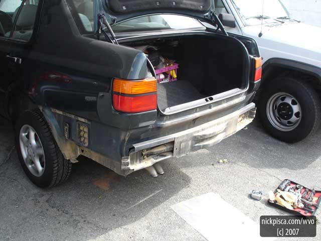
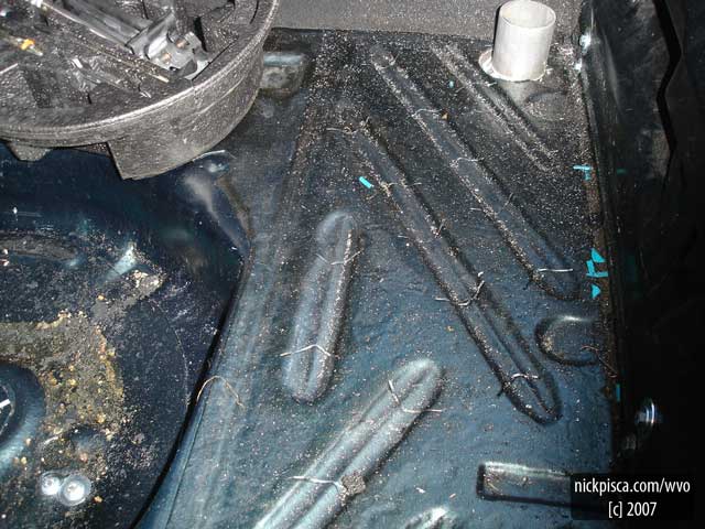
BUMPER COVER REMOVED:
In the image above, you can see the slider mount in the triangular space behind the driver’s side rear tire. It’s about the size of a deck of cards.
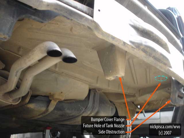
POTENTIAL AREAS OF CONFLICT:
In order to obtain tank capacities of over ten gallons (37.8 liters), there would have to be some demolition to the car. These would be in inconspicuous areas. Also, obviously there would have to be a hole through the trunk for filling and mounting would come from the vertical webs surrounding the tank. My intuition would suggest that this mounting technique would work better than thru-bolting through the trunk floor, to minimize deformation of the trunk metal and/or pulling through. Also, a more experience mechanic my use the mounting areas for the diesel tank, for they are far thicker and made for supporting heavy tanks. But I wanted to align my driver’s side strap with the to-be-removed bumper cover flange, so that this strap would play a dual role: to support the tank and replace the flange connection.
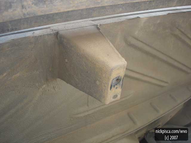
BUMPER COVER FLANGE:
This is the existing bumper cover flange that needs to be removed if you want to use a tank longer than 23.5 inches.
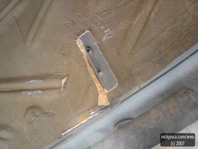
I used a reciprocating saw the tore out the trapezoidal web. But after pulling that out, I realized that this flange is held in by two pop-rivets. (see image below)
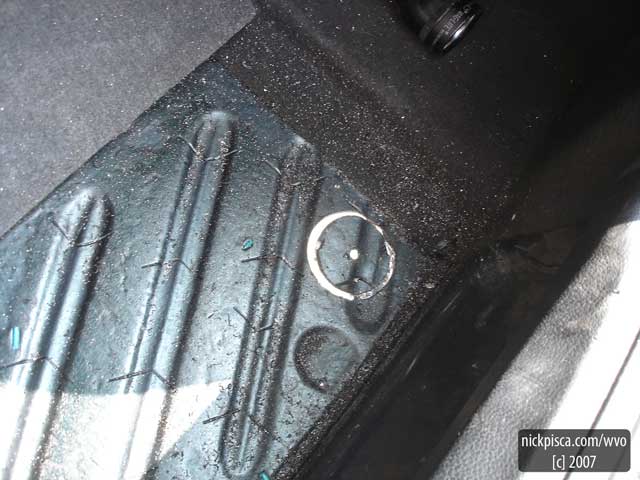
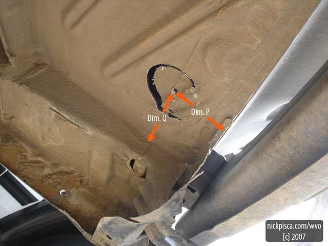
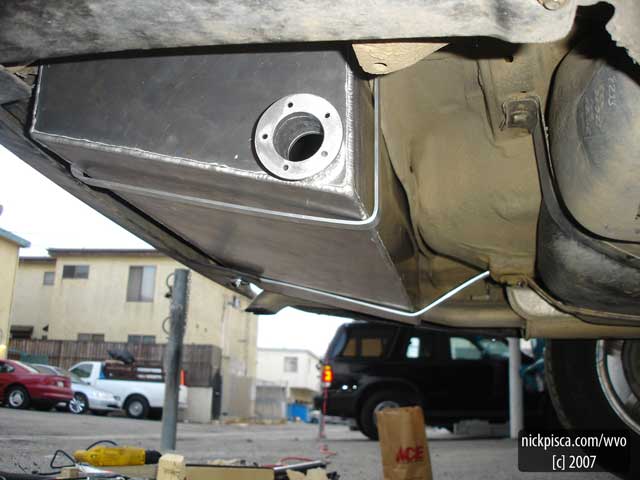
NOZZLE HOLE:
The location of the nozzle hole was a sort of guess at first. I tried to correspond it to the dimension on my tank specs, but due to the fact that it may not nest exactly in the corners, it may not fit correctly. I picked a point that was a happy medium and it set perfectly on the first attempt. I don’t have Dimensions P or Q on me right now, but I can post that later.
Also, in this image and previous pics I mention the ‘Side Obstruction.’ This is the slight bend in the body to the passenger-side direction of the nozzle hole. I didn’t see this when I initially measured for the tank, but this obstruction is a curved piece of metal that needs to be cut back to accommodate the tank. You can see I made two simple cuts with the saw that allowed me to pry back the metal. It doesn’t need to be removed, but just out of the way.
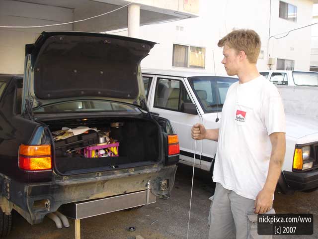
SECONDARY TANK INSTALLATION:
Eventually it got easier to work on this if I ripped off the bumper itself. It’s very easy to do and requires the removal of just four nuts.
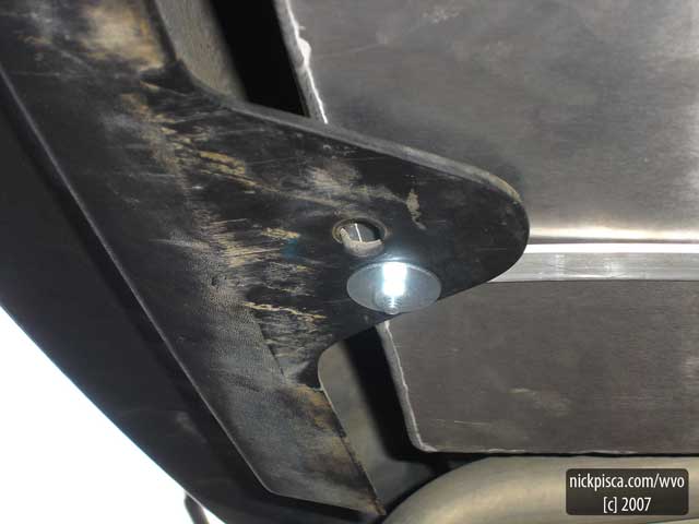
I have a tracing of the tank straps if anyone wants to copy them exactly. They are just cut from three foot 1/8 inch thick aluminum strips from B & B Hardware. I bent them around a steel pole near my work area and thru-bolted them into the trunk web and body. Also, you may need to flip back the top at a 45 degree angle for a half-inch (you can see it at the top of the strap in the image above.) This will keep the end from scratching the paint off and there is a slight angle to the body that requires a kick-back.
When this photo was taken, I was about to install the second aluminum tank strap. This strap requires some careful placement, because it will be supporting the tank and connecting to the bumper cover (where the flange used to reside).
Be sure to align it with the existing bumper cover connection – you’ll see further down the thread, but I was off by an inch and had to re-drill a new cover hole.
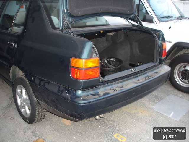
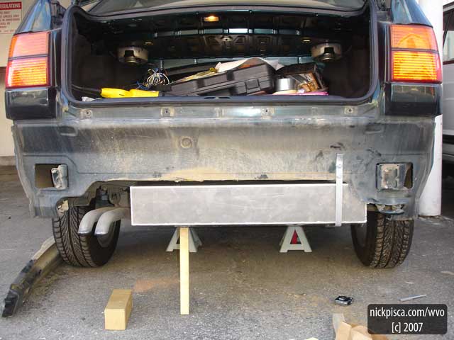
BUMPER AND COVER REINSTALLED:
I replaced the bumper cover and it looks as good as new. My neighbors said they didn’t even notice a new tank was there.
HOTFOX INSTALLATION:
One thing to note: Make sure to install your HotFox before mounting the tank. I thought I could just slide it in after the tank was set, but my bumper cover got in the way. It was a pain in the ass, but if you just pull some of the bolts on the passenger side of the bumper cover, you can slide the plastic far enough up to pass the HotFox though.
Part of the reason for the horizontal mount was to have the option to drain the tank if necessary. I can pull the HotFox out, but because of this obstacle, it will just slide up to the bumper cover.
Also, I had to redrill my HotFox mount holes, because I specified a small dimension for fabrication.
LOCATION OF NEW BUMPER COVER CONNECTION:
As I mentioned before, I tried aligning the new cover connection to the old flange location, but was off by an inch. I was able to re-drill the hole and use an over-sized fender washer to evenly distribute the load over the plastic. Since it was much closer to the edge of the plastic, I didn’t want to risk any tearing during driving.
This space looks deceptively larger than I expected. 🙂
Rear Components and Bundle Installation:
The following images show how the components and bundle were installed.
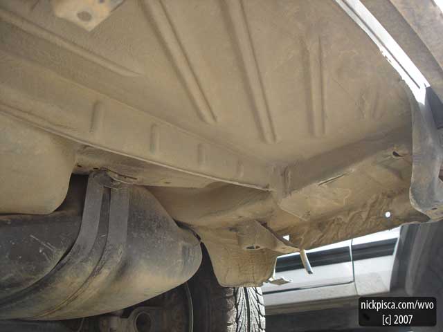
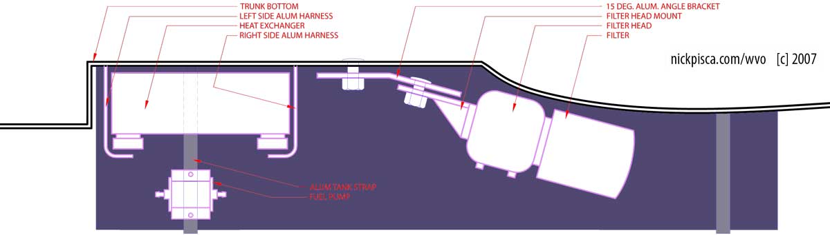
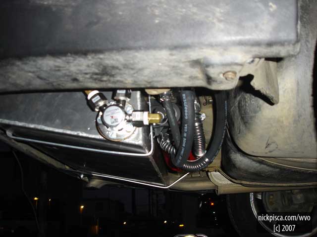
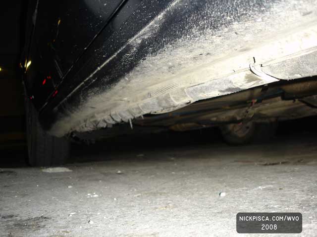
EMPTY SPACE UNDER THE CAR:
When I first planned out the rear system, I speculated that the components (a heat exchanger, fuel pump, and filter head) would all fit besides the tank directly behind the rear tire. Once the tank was completely installed, it was apparent that this would be impossible. The HotFoxfittings would obstruct all side-layout scenarios, so I moved to the space between both tanks under the car. This space was eight inches deep at its highest point, which forced the filter head to be horizontally or angle mounted. The filter head was 9 inches tall.
The filter head required a custom metal angle to set it at fifteen degrees. I wanted it to be as steep as possible to reduce spilling oil when a filter required changing, but fifteen was the most I could get.
Next, I placed the 20-plate heat exchanger up against the tank and underside of the trunk floor. To secure it, I fabricated two bent aluminum strips on each side. If I needed to pull it out for some reason, I could just push back this harness. They hook and connect to the top of the exchanger, which is upside-down.
I thought the fuel pump could still be mounted on the side, but that proved difficult again because of potential hose kinking. A spot directly the heat exchanger worked best. Glenn predicts my cheapie fuel pump will give out soon anyway, so mounting where it’s easy to remove would be good. I didn’t even bolt it in place; the mounting was accomplished by using some aluminum wire loops.
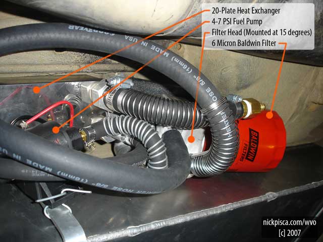
HOSE ROUTING:
Since most of my fittings are all pointed downwards, I needed to be creative to avoid kinks. AutoZone sells Goodyear brand heater hose coils that are meant to hold a specific bend in a specific location. They slide onto the hose and have a metal backing that retains the desired shape. This is important for my design, for I can’t have any hoses dip below the tank; if it did, not only would I lose all my heat, but also it could get caught on something when I drive.
I found that these coils have a secondary effect that reduces kinking for moderate turns. Since the store-bought coils still have a little play with the hose, it can still kink or stretch, so I used some of my aluminum wire to produce my own. It doesn’t have the backing, but it still works really well if it’s snug.
I would have used more 90 degree bend fittings, but in most cases, it wasn’t possible. The heat exchanger had some crazy custom hose fittings that I could replace.
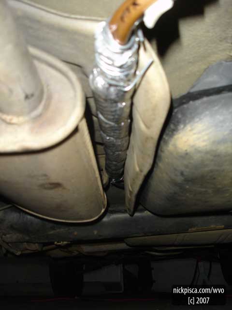
EXHAUST SYSTEM BYPASS MINI-BUNDLE:
For most of the bundle, I used large extruded insulation with Hose-On-Hose (HOH) heating. This insulation had a wall thickness of 3/4” and averaged a diameter of 3.” There was a small distance from the back of the car to the suspension system that couldn’t accommodate this large bundle. So before I installed the large insulated HOH setup, I made a thin segment out of 3/8” copper and aluminum bendable pipes. Just in case you don’t already know, you shouldn’t use copper hoses or fittings for the VO system. There has been a lot of research on this topic and copper can react with vegetable oil.
This smaller bundle is probably a better conductor of heat transfer anyway, because I connected the two copper and single aluminum tube with silver solder.
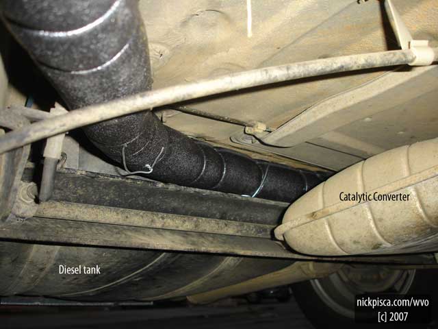
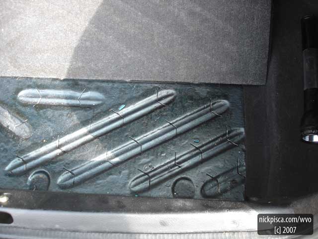
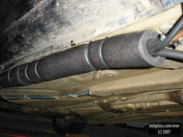
START OF THE BUNDLED TUBES
Since my major HOH bundle starts by the muffler, I was able to make some steep bends in the copper and aluminum tubes from the mini-bundle. This lifted the tubes up against the floor boards to clear the suspension system. As you can see, I wanted to have a lot of insulation to protect the bundle. These were 6-foot segments from B & B Hardware and I used zip-ties to make an A-A-B pattern.
The make-up of the bundle comprises three 3/8” fuel hoses (coolant-in, coolant-out, & fuel-supply) and a 5/32” vacuum tube for a VO return.
POTENTIAL REWORK
The only part of the system that makes me cringe is the mid-section of the bundle. There wasn’t a lot of room for a three-inch diameter tube to go for this 3-foot distance. If you look at Jeff’s configuration, he ran HIH and that afforded him a low-profile system. On mine, it does hang down pretty far. I’m tempted to remove this section and make another mini-bundle to run closer to the floor boards.
If I had to start from scratch, I’d contemplate doing the whole bundle with aluminum 3/8” bendable pipe. It’s only 89 cents a foot and if you can solder certain places together, you’ll essentially have a twenty-foot long heat exchanger. Glenn said it would be a pain in the ass to route the lines, but since it’s not being tracked inside the car, I don’t think it’s that difficult.
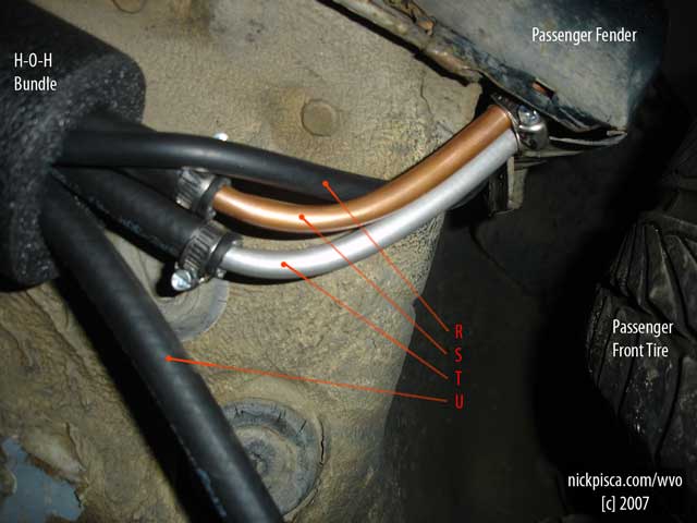
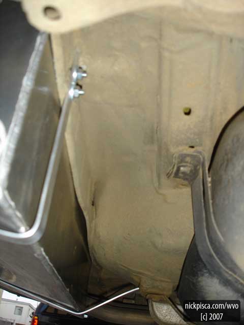
COOLANT RETURN SPLITS AWAY:
I split the coolant return away from the bundle right behind the passenger-side tire. This saves some space when I set up the front heat exchanger. From the Image above:
- R: VO Return
- S: Coolant Supply
- T: VO Supply
- U: Coolant Return
Once again, I used a section of the copper and aluminum bendable hose to manage the transition through the fender. If I just bent the rubber hose into the fender, it could kink. I re-bundled the three remaining tubes after the interstitial metal segment. Also, this metal area is insulated with reflectix (not in the picture.)
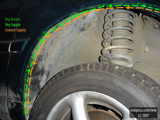
FENDER AREA:
This was a good find for hiding the bundle. If you remove the plastic inner fender, there is a whole bunch of room for not just the bundle, but if wanted to install a third heat exchanger, this would be the place. I’m even tempted to move my front heat exchanger to this location, because the upper left side has a lot of extra space. I don’t have an image of the system with the inner fender removed, but this picture shows how the three tubes work.
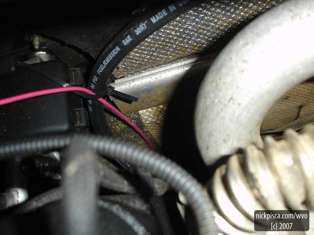
COOLANT RETURN:
The coolant return hose emerges up the firewall and connects in the heater core hosing in a series configuration with a simple brass 3/8”-to-5/8” reducer. The coolant supply hose (not pictured) runs continuously around the engine and follows the VO lines from the selector valves to the rear “mini-bundle.”
Later, I came back through these areas and added some lower profile extruded pipe insulation to this line. Due the conversion, the heater core is now the last element in the series circuit. Saving as much heat as possible will decrease my warm-up time.
Also, the image displays the 14-gauge pink wire that is the load for the fuel pump in the rear. I ran it from the back to the front, which may have been a mistake. Later I found that the Jettas have a few extra slots for diesel supply and return. Look in the engine compartment near the diesel can filter; if you see a blue plastic line, follow that to a metal tube that runs down through the floor boards. If you can fish your electrical down this path, you can have a really clean system.
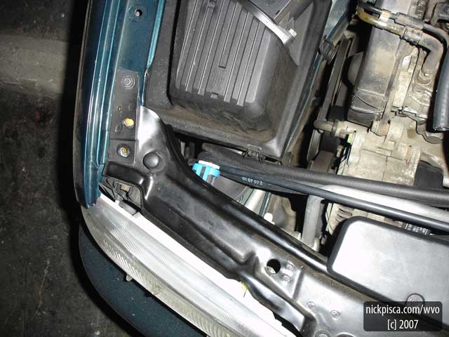
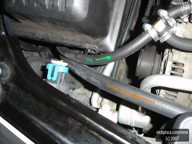
END OF THE BUNDLE:
The bundle completes it run in front of the air filter housing. I found a reasonably-sized hole that accommodates an uninsulated cluster of hoses. I ran a 5/8” hose from the heater core for the first part of the coolant supply line because I have a theory that the thermal mass will retain more heat. At the bottom of the air filter housing, there is a heat exchanger that you’ll see later in the thread. The heat exchanger has a 3/4” coolant fitting so this works pretty seamlessly coming directly from the heater core hosing (avoiding a reducer).
This was all post-insulated once the engine portion of the conversion was completed.
Engine Compartment Modifications
The front of the car has a hidden heat exchanger, two selector valves and some fuse housings.
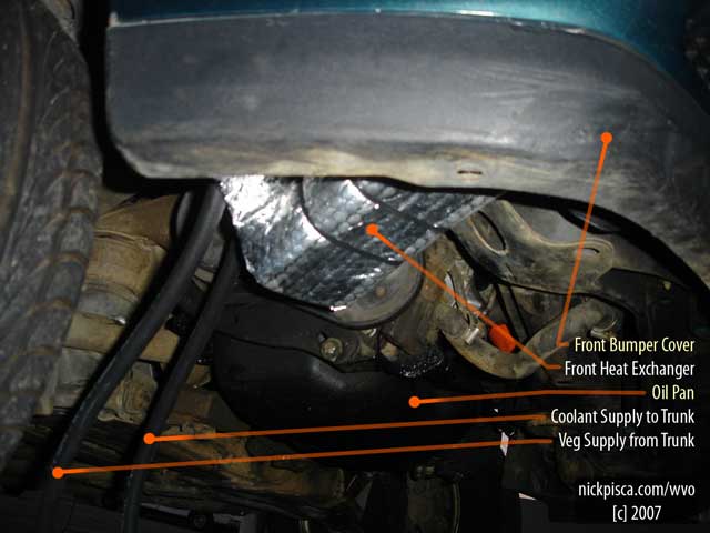
HEAT EXCHANGER LOCATION:
In the planning for the conversion, I found this little space in the front clip directly underneath the air filter canister. It looked quite big, but once I obtained the heat exchanger, it appeared to be tiny. I was able to manage it into place, but it forced some pressure on the outlet hoses. After some miles, I started leaking some G12 with every stop. I pulled it out later that week and tightened down the clamps and fittings. I have plenty of Teflon tape on the FPHE and they are tight, but I’m suspicious that the unit has a fracture.
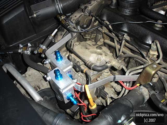
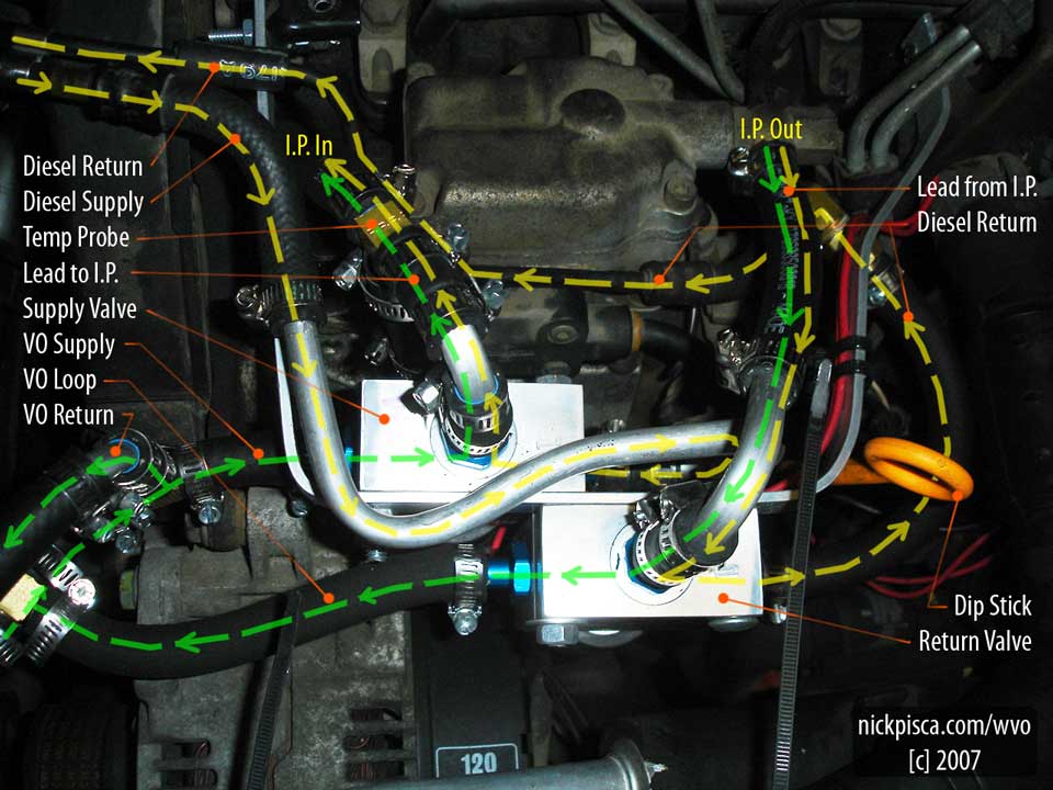
BEGINNING STEPS FOR VALVE INSTALLATION:
First thing, I wanted my valves to have a secure armature so they are stabile. By bending an 1/8” x 3/4” x 24” thick aluminum strip into a choppy “C” shape, I was able to cantilever this off of the two brackets meant to support the plastic VW TDI cover. If I wanted, I could still reinstall the VW TDI cover, but I’ve left it off until I’m sure the system is completely bug-free. The C-armature has a jog on the driver’s side to still allow access to the motor oil dipstick.
Three thru-bolts held down the Hydraforce heat exchangers just above and right of the alternator. They are out of the way and still need only a four inch length of fuel hose to reach the IP supply and return nubs. We got a deal online for the valves, but that meant our blue fittings didn’t have a 90 degree bend. Annoyingly, they shot out like a starfish and robbed the compartment of room. I needed to save space without the possibility of hose kinking or having a blobby mess like in the back of the car. (You’ve probably noticed that I’m abnormally suspicious of “kinking.” I mention this because on our first trip across the country on VO, we had a number of rubber hoses kink shut after some use. This was problematic, because when Glenn built the car, I’m sure that the hoses initially bent smoothly. So those kinks occurred down the road, and when you’re 3000 miles away from home, it’s troublesome.)
On the upper-left of the image, you’ll see the VO supply line which splices off to both selector valves. These are the default-ON position for each valve and if power fails or they go bad, the valves will fall back onto default-OFF corresponding to diesel. The valve closest to the IP is the supply valve and the other is the return. I have the limited return reconnect back into the supply line so I’m always recirculating my heated veg and no losing heat back to the tank. You’ll also notice that I have my temp sensor just before the supply valve. Later, I moved this to the IP supply feed, so I can measure temp of the diesel and VO. The existing brass tee was relegated to manage the VO return, connected to the bundled 5/32” vacuum tube. I pinched off the fitting to resist the pressure of my pump, but when you go back to the tank, there is still a good deal of liquid moving through my vac hose.
Lastly, the only downside to this layout was the diesel fittings for each valves emerge 180 degrees from the diesel filter.
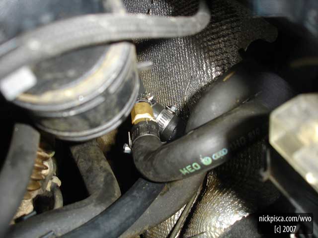
COOLANT SPLICE:
I realize this is a horrible image, but the center hose is half of the old heater core hose. Since the coolant return came up along the firewall and the coolant supply line wrapped around the engine, it was easier to cut the existing heater core hose in half and use brass reducers to match up directionality of flow. You’ll notice that the darkest hose (center, below) is the coolant supply hose at 5/8” diameter. It’s connected using a 5/8” 90 degree plastic heater hose bend from Kragen, to the right of the brass fitting in the middle.
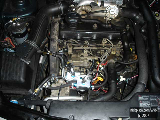
THE COMPLETED CONVERSION:
I was too excited to wait and try a diesel (with diesel service) test run on my second tank. After vacuum pumping out all the air in my diesel system, I fired up the engine with some trouble. I thought I had a leak in the diesel hose, for I reused my old feed lines from the diesel filter, and they were pretty cracked. To check if this was the problem, I cut a direct segment from the filter to the valve. Still, if I let the engine sit, the IP would lose its prime and take some cranking to start. I forgot to mention that I had to buy a new battery from Kragen, because I let my car sit for four weeks without running. The darn thing wouldn’t take a charge and it was already pretty old.
Still, I had a leak somewhere in the diesel system that depressurized my fuel lines. Once I pumped the system full of SVO, it filled against the other side of the supply valve and it never lost its prime again. I think the valve may be water-tight but not air-tight, and since there is fuel at both ends, it will hold for now.
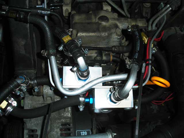
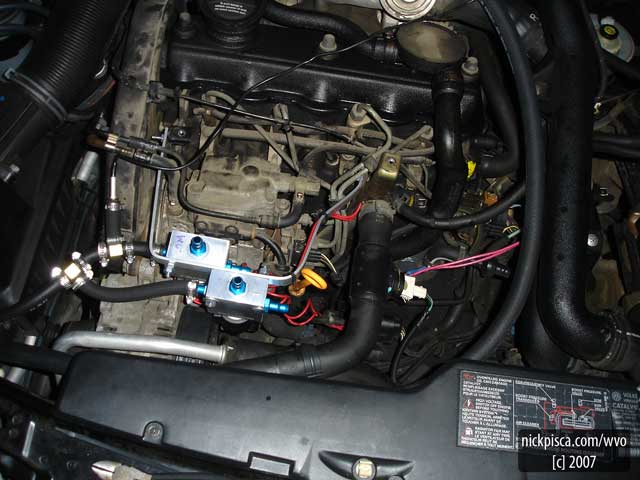
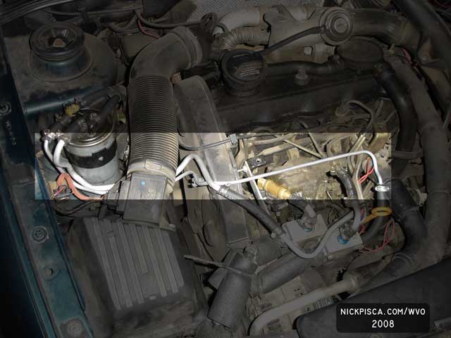
CLOSE-UP OF THE FRONT SYSTEM:
- The #1 trick for a VO road trip: Bring BabyWipes.
- The #1 trick for VO conversions: A brake-line pipe bender.
You can really make some clean and complex bends with some cheap metal aluminum pipe and a simple bender. Notably, the center aluminum pipe was designed to bend up and between the valves, jut down toward the engine and cut back to match up with the valve fitting. It’s almost if you had an “S” shaped pipe and twisted the top away from the bottom. Also the pipe bender let me make cheap 90 or 90+ degree bends without kinks. Sometimes the brass bend fittings would cost over 4 or 5 dollars. Making your own with a bender will cost a few cents.
POST-INSTALLATION MODIFICATIONS
Update February 2008:
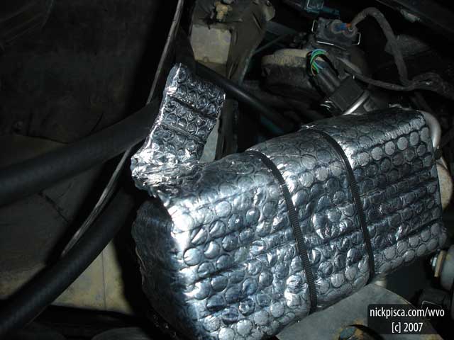
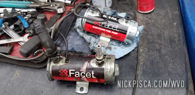
BUSTED FUEL PUMP:
In January, I had a failing switch that had a loose internal connection. Every bump would kick off the VO pump and switch-over valve. I replaced the switch, but it may have put stress on the cheapo fuel pump I acquired from Kragen. Glenn said that my pump would wear out in six months because the plastic pumps are shoddy. I showed him; it lasted 7 months.
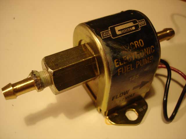
I replaced it with a Mr Gasket Micro Electronic Fuel Pump, and it seems to be more trustworthy and durable. They had this at a Pep Boys SuperStore and it had metal components and casing. It’s still rather small and has a range of 4-7 psi, but it should last longer. Glenn stated that I’d need a larger pump if I want this to last.
The pump replacement took only 30 minutes and it was minimally messy. I designed the system to have the pump near the bottom of the kit, so it was easily accessible from the bottom of the car. Also, I installed an extension for the ground so that I don’t have to remove the bolt located at the top of the assembly.
Update Late February 2008:
BUSTED FUEL PUMP (Part 2):
So much for Mr Gasket. I ran this for 200 miles and it seized up. That’s extremely poor design, because I would assume a supplementary fuel pump would fail with the valve open, so the other pump could still force fuel to the IP. After I ripped it out of the system, I tested it at the battery terminals and the thing wouldn’t move.
I’m hesitating to state that the pump is at fault, for I could have fried it electrically. However I doubt this because I had a 5 amp fuse in line to the pump, and that’s relatively light.
So now I have to concede that Glenn was right and I should have bought the heavy duty pump from the start.
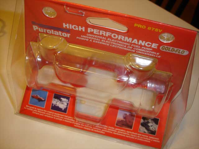
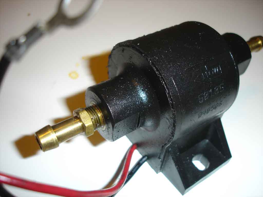
Replacement Pump:
I purchased this heavy duty pump at Pep Boys. Prior to reinstallation, I decided to drain the tank, for I estimated that I had about two gallons which should be fast. I pulled the 3/8″ fuel hose off the busted second pump and let it drain into a half-gallon milk jug. It seemed to drain slow thru the hotfox (about 1/2 gallon per 2 minutes). Purhaps this is the reason why the previous pumps failed? I didn’t have to pump the veg out of the tank–it drained ok, but I envisioned it emptying out of the bottom of the hotfox faster. I suspect a full tank would flow ultra fast.
This larger pump fits nicer than the previous two in the space allotted. It has elbow fittings that don’t force the IN and OUT hoses into kinks. After setting it up, I rested it against my aluminum tank and turned it on–it jostled back-and-forth with such force to pound against the tank. I added some insulation to the space inbetween and it’s nested directly below the FPHE.
Update March 2008:
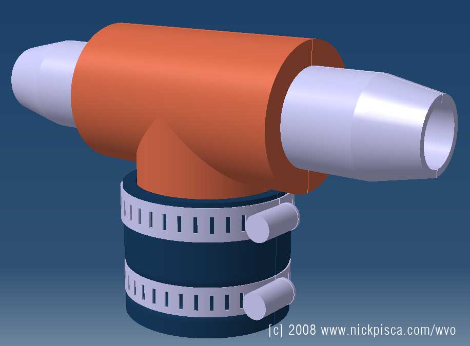
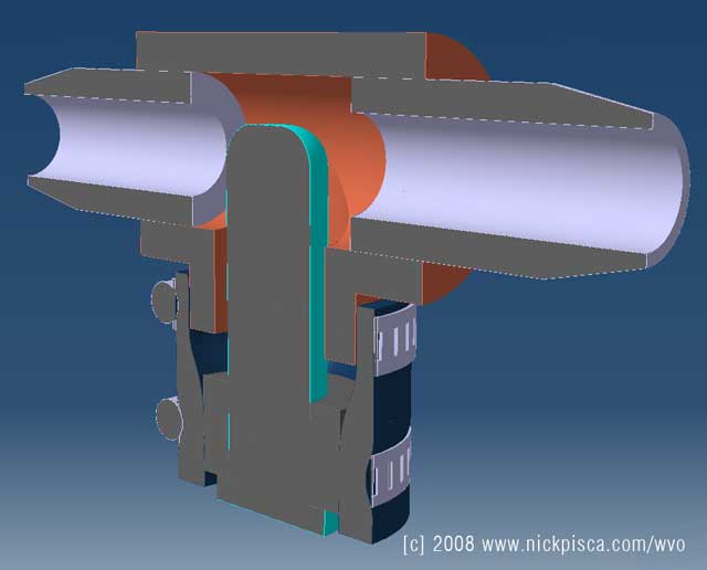
New Temp Sensor Housing :
I was getting minimal readings from the existing workaround for my temp sensor probe. I decided to rework this so that more of the probe was submerged in VO. The images above are a 3D model of my current housing; I wish there is a cheap inline-temp probe housing, but I couldn’t find one on the market.
One drawback to this housing is that it’s brass, so I need to periodically check to make sure that no chicken-skin resides in this “T.”
Update April 2008:
Low Profile Aluminum Tube Bundle:
Here is an image, where I decided to replace my shoddy rubber HOH bundle under the passenger-side front and back doors with aluminum. This reduced my exposure by nearly 2 inches! I sit in the little groove where the lower panel connects to the underbody.
I hope that this aluminum HOH will transfer heat better as well as be more durable.
Update July 2008:
Low Profile Aluminum Tube Bundle:
After the trip to Alaska and back, I had a substantial Diesel leak. I constantly lost my prime and it took several seconds of hard cranking to start. I thought it was the plastic connector on the return at the fuel filter, because we had to replace the stock plastic lines in British Columbia with 3/8″ rubber hose and it looked like there could be a slight fracture in the plastic. After investigating the price of the plastic connector ($38 at the VW store in downtown LA), I decided to see if replacing the rubber lines would fix this. Since this was going to be a complete overhaul of the front end fuel lines, I decided to use the old plastic lines as a pattern. The brake-line pipe bender made a sweet cheap replacement with 3/8″ and 5/16″ bendable aluminum hose.
I really think that newbie and existing conversions should consider all HOH bundles and individual fuel and VO lines to be bendable aluminum. It removes several of the head-aches and leaves you with a durable line resistant to rubber wear. Also, it’s cheaper!
Update March 2009:
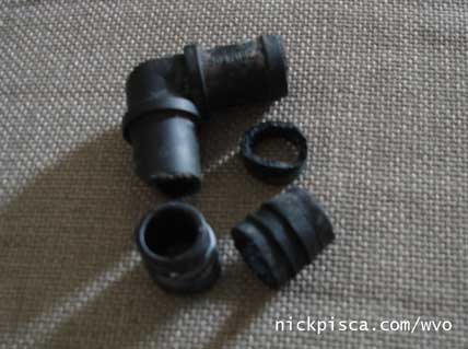
Plastic Elbow Connector Breaks Easily:
This was terrible. I went out for a weekend drive and a mile from my destination, I smelled anti-freeze. I managed to limp the car all the way there, but lost all of my coolant on the road. The leak occurred at a plastic elbow connectorI used to splice into the heater core line. When I reached back to check out the hose, it was originally just a hair-line crack. But after pulling on the hose, it easily broke off into the end of the heater hose. While pulling the broken element out of the other side, that side too broke off into the opposing heater hose end. What junk.
Luckily, I had a few friends there that lent me access to their wood/metal shop. We found some scrap metal piping, with one with a slight bend. After some chopping and sanding, we had a great substitute splice. (No picture of the new splice)
Update November 2011:
We revamped the whole setup. Dropped the tank, cleaned up the exterior, drilled a hole for a digital tank sender, and cleaned up the hotfox unit. Also, we installed some digital pillar gauges and rewired the setup. Now we have a digital percentage of the tank level!!! Woo hoo! No more calculating the fuel level by counting miles.
We also eliminated any and all brass fittings. Brass, copper, and steel are notorious for causing polymerization, so I converted everything over to aluminum. Also, I replaced the 20-foot long rubber fuel hose bundle with four segments of HOH Aluminum piping. It’s more durable, doesn’t kink, and allows for continuous heat transfer. Much much better than rubber hose.
Update March 2017:
Copyright Biotuning.co.uk.
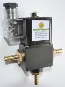
I had one of my hydroforce valves go out on my Jetta. Not too bad, because I bought these in 2008 in Salt Lake City and they lasted for many years. I tried to find a replacement valve, but the prices at Hydraforce had gone up. And with my IDI van, I had been using a different style valve (see image to the right) which appeared to work better and last longer.
To keep things consistent, I decided to switch over all my selector valves to this style on both vehicles.
Update October 2019:
I was having some odd power issues on the highway. I thought maybe the veg-side fuel filter was clogged, so I changed it out. That didn’t seem to fix it. I wasn’t getting any return-side fuel flowing out of our return spout. To isolate the problem, I warmed up the circuit. Then I disconnected the fuel hose to the supply selector valve, and flipped on the fuel pump. Found the problem: the veg pump wasn’t pushing fuel.
Since the previous pump lasted over a decade (not too shabby), I decided to buy the same pump. It worked well for a long time. I swapped over the aluminum fittings and ground wire and returned it to the spot near the FPHE.
While I was replacing the fuel pump, I figured it might be time to check over the whole kit. As far as I could tell, it’s all working fine. The FPHE had some corrosion or build-up on the passenger side (not sure from what, because nothing was rubbing on it), but maybe the seals on the fittings were starting to seep.
Also, I had a bit of a drip from the ear-flange on my horizontally-mounted hot fox, coming from the cork gasket. I retightened the mounting thru-bolts and cleaned up all the build-up.
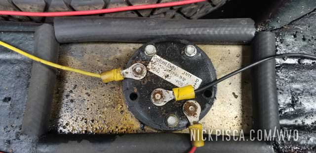
Lastly, my veg fuel level sender wasn’t working for a few years. It worked fine ever since I calibrated it in 2011, but for a long time, it was reading all odd. Basically, the gauge read F when the tank was about 60% full, and it read 40% when it was near empty. I tried to recalibrate, but nothing worked.
The original sender for this Jetta conversion was from Centroid Products. Pretty simple design, it uses capacitance of the fluid to determine the level of the fuel. It wasn’t calibrated for biofuel, but with their custom 6-second jump technique, you can force it to understand a full tank of any liquid.
I also used a Centroid sender for my IDI Van. Both original senders died after about 5-6 years, with them sending erratic signals to the gauge. I even replaced the gauges, assuming the high-quality-high-cost Centroid senders would be fine. That didn’t help. Then, in an attempt to save shipping, I ordered two new senders from Centroid in 2018 and put the longer one in my van. After several days of calibration, nothing seemed to work. I was getting pissed, because they changed the design in 2013, and clearly this new version didn’t work right. I even sent the van sender back to Centroid with a sample of my biofuel, in the hopes they could use their calibration to custom set it up for me.
Even after that, it never worked right, and I mistakenly overfilled my van tank twice. That is horribly annoying because it makes a huge mess. The gauge now reads 87% when the tank is full, but not always, leaving it a guessing game if I’m close to full or overfilling. Also, every time the gauge reads a number ending in “1” like 11, 21, 31, 81, etc, it would flash around to odd numbers in the middle of my drive. I’m kind of pissed, because the techs at Centroid keep implying that I made some kind of calibration mistake, but nothing has changed from the previous sender. Same wiring, same gauges, same power supply, same everything. All I did was swap out the units, and calibrate it based on their directions. If their quality had stayed the same, it should be a quick job. But it wasn’t working.
Even though I had a huge issue with the new IDI Van sender, I pulled out the old sender on my VW, and installed the new Jetta Centroid sender. I got it calibrated for a full tank, and of course, the gauge didn’t read it right. I contacted the Centroid Techs again, and they gave me the runaround again. The gauge kept reading 99% no matter how little fuel was in the tank. The new senders have a 20-second calibration, but every time I tried it, it wouldn’t display the correct volume in the tank.
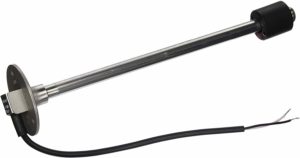
Copyright: KUS USA SSS Fuel & Water Level Sensor, found on Amazon here.
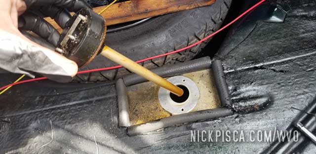
I used to recommend Centroid Products all the time for anyone using a custom tank. They used to be awesome, but something changed with their 2013 design. It rarely works. After they kept implying that I did something wrong, I finally broke down and bought a MUCH-CHEAPER KUS float-style sender that I wired up outside the tank. I slid the float up and down and the gauge read 0-100% perfectly corresponding to the location.
That proved the Centroid units (even though they were brand new right out of the box) were broken. Both of them. I’m done with using them, and I highly discourage anyone trying to use them.
Instead, I will currently support KUS USA and their float-style senders. It’s a simpler design, doesn’t require 12V power, and as of the last 500 miles, it has read the tank level perfectly. Also, their senders are stainless steel (not mild steel or copper) so they don’t react with biofuel to clog up my tank.
I cleaned up the surface of the tank too, and used fuel-rated RTV in conjunction with a cork gasket to eliminate any leakage on the top of the tank. As you can see from the pictures above, my tank had some top-level seepage that was starting to stink.
Now with the whole biofuel system tuned up, it’s all been running well.
Legacy:
As of November 2019, this Jetta is still running fine on WVO. There have been other fuel hosing and coolant hosing mods, but the majority of the kit is pretty much the same as this article. Almost surpassing 300,000 miles on the odometer now.
Disclaimer: We are not responsible for anything you or anyone does to your engine, vehicle, yourself, or others and any property as a result of your modifications. You are responsible for your actions.
Copyright Nick Pisca 2007-2019 Waste Vegetable Oil Fuel Travel and Awareness.
