If you have a 1980’s Ford diesel van, you probably have a faulty fuel gauge. There are many reasons why this may occur:
1.) Your sending unit has failed.
2.) Your float has a hole and is full of fuel, thus reducing its buoyancy.
3.) Your gauge is faulty.
4.) Your wiring is shot.
This article is going to focus on the topic of replacing the sender. For most IDI truck owners, replacing the fuel-pickup-sender unit is a simple task. They just order a new sending unit and install it. However, for IDI van owners, the sending units are not the same as the trucks. If a van owner purchases a diesel truck unit, it will not function properly.
Ford designed the IDI trucks and IDI vans to have different resistances (in ohms). Trucks had “magnetic” gauges where a full tank transmitted 160 ohms and empty tank transmitted 15 ohms. IDI vans had “bi-metal” gauges where a full tank trasmitted 10 ohms and an empty tank transmitted 70 ohms. [citation: Chart CK10440-1A of the official 1988 Ford Service Manual] This tutorial is based on research found on the Ford-Trucks Forum.
Therefore, if a van owner attempts to install an IDI truck fuel sender, it will result in incorrect resistance readings and an inversion of the directionality. As of 2017, no parts supplier stocks replacement IDI van fuel senders. There are custom services that rebuild your old senders, but these are crazy expensive and take weeks of down time. What can an IDI van owner do?
Luckily, in the 80’s, most of the gasoline fuel senders used the “bi-metal” resistance. Some were 10:70, 10:73, or 10:80. Even though these are different, they are close enough for the purposes of a 30-some year old van.
For this tutorial, the project vehicle will be a 1988 Ford 7.3 IDI Clubwagon XLT. It will focus only on the rear 22-gallon tank. Different van models and trim types may have deviations from this tutorial. Revise your project accordingly.
This tutorial is for novelty use only. We take no responsibility for any damage you do to your vehicle or yourself or others. There is no warranty. We assume no responsibility.
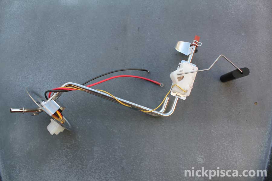
For this 1988 IDI van, the rear 22-gallon tank uses a large sender and fuel-pickup. For this project, a Dorman 692-115 Fuel Sending Unit is going to be modified and installed to replace the old diesel stock sender. This unit matches the diameter of the hole in the fuel tank. If your tank has a different diameter hole, then you need to find a different sender unit.
Preparation
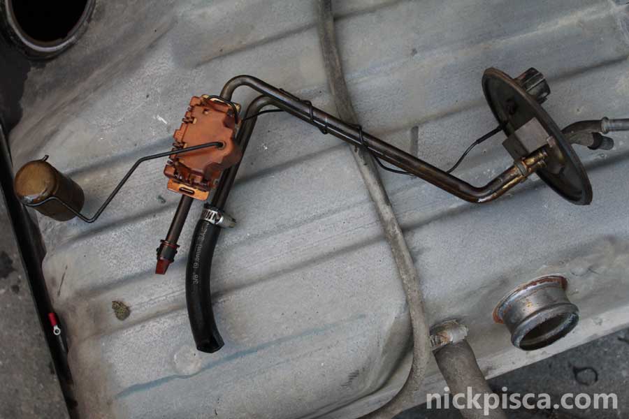
Start the project by draining or siphoning the fuel from the tank. Ideally, you want a light and near-empty fuel tank to make the uninstallation simpler. Once empty, undo the hose clamps for the fuel nozzle hoses. There should be two hoses, one about 1″ in diameter and another about 2 1/2″ in diameter. Pull the hoses off the tank and set them aside. Then undo the fuel supply and return lines located at the front top of the tank. There is also an electrical connector near these fuel lines, but you can leave it installed while dropping the tank. Near the rear of the tank are two long threaded bolts connected to the tank straps. Unscrew the holding nuts until the straps become free. Pull the tank down to the ground careful not to put too much force on the electrical connector and wiring above. Carefully undo the electrical connector with a small screwdriver, and pull the tank out from under the van.

Extracting the Old Sender
Using a screwdriver, carefully pry the retaining disc counter-clockwise. It may require a bit of tapping until it spins free. Eventually, the retaining disc rotates free and set it aside. The new sender should have a new replacement retainer in the kit. Carefully extract the old sender out of the hole. It will be a tight squeeze and will require some angling to get it out. Do not just pull hard; find a route that will allow you to remove it without a lot of resistance.
When I removed my sender before, I checked to see if my brass float was flooded with diesel fuel. Your float may be fuel-logged and has no buoyancy. Check your float first, by unsnapping it from its wire holder. Shake it a bit and see if any fuel is sloshing around in the cylinder. If yes, located the hole, allow it to fully drain overnight, and seal the hole with solder or a diesel-resistance epoxy. Then reinstall your sender, because that is a simpler fix than this tutorial. However, my float is not full of fuel, so I checked the resistor. The fuel sender uses a variable resistor that is adjusted by the wire holding the float. As the fuel level changes, the float raises or lowers, adjusting the wire, and adjusting the location on the variable resister. That is registered on the guage as a spectrum between “E” and “F” on the instrument panel.
As I moved the wire back and forth, I felt almost no friction between the resistor and its connector. That basically shows that the electrode has been worn down to nothing. If you have a new sender handy, try moving its wire; you would notice some slight friction as it moves, showing a solid electrical connection. If one removes the plastic cover, he/she would see worn plates with no metal to conduct the resistance for the gauge to read. The only way to fix this is by replacing the unit.
Testing the New Unit
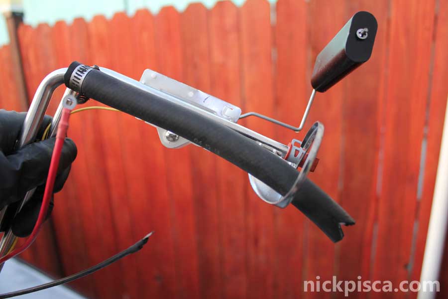
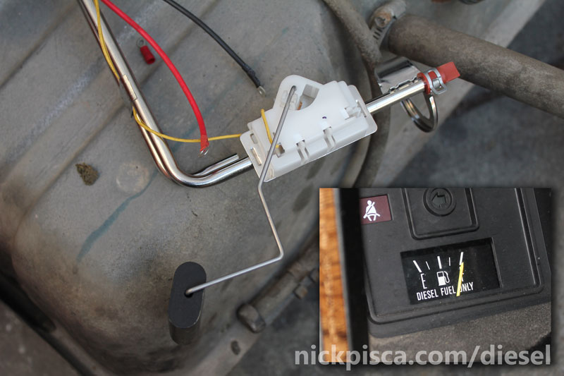
Since the gasser sending unit is different than the diesel unit, some things need to be addressed. First off, the gasser unit is designed to hold an “in-tank” fuel pump. IDI vehicles have their fuel lift pumps near the engine, so a lot of the pickup will be ignored. Since the fuel pump is not going to be used, this install will require a longer section of fuel hose to be installed to act as a straw to reach the bottom of the tank. Also, there are two wires used to power the in-tank pump that will be ignored for this tutorial. To convert this gasser fuel pickup to the diesel version, just cut a section of 3/8″ fuel hose and clamp it to the supply side tube. You can tell that it is the supply side tube because it does not have a red crimped rubber thingy on the end of it. Be sure to remember to cut a “v” in the end of the fuel hose so that it does not suck tight to the bottom of the fuel tank. Also, please test your fuel hose to make sure it is not too long or short for the tank, by placing it in the hole in the tank and verifying that the hose does not bind or sit too high. (Jayro, who was the inspiration for this project and did a lot of the leg work for testing this, suggests that installing in-line fuel filters prior to the fuel selector valve is prudent whenever replacing the cone-of-failure with a section of fuel hose in a tank.)
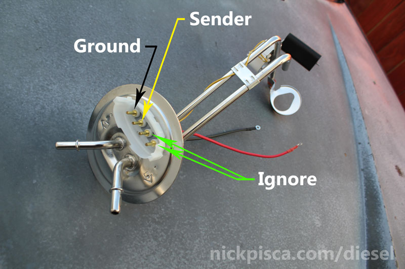
The old diesel fuel sender uses only 2 wires to send the resistance, but the gasser unit has 4 connectors. The only wires needed for this project will be the yellow and black wires, which come from the resistor and the ground for the system. The other two wires can be ignored. You will want to make a solid connection from these two electrical prods; I used a spade connector crimped down on the copper prods, but a more long-term solution would be to solder these spade connectors to ensure durability.
To test if your new sender works, connect a short section of wire from the orange (non-black) wire from the van connector to the yellow connector prod on the tank sender, and the black wire from the van connector to the black connector prod on the tank sender. This will allow you to turn on your van (just “key-on,” do not start the engine, and make sure to turn the selector valve to the “rear” tank), and adjust the fuel sender to test if it is working to its capacity. Moving the float all the way down should correspond to an “E” on the gauge, and moving the float all the way to the top should correspond to the “F.”
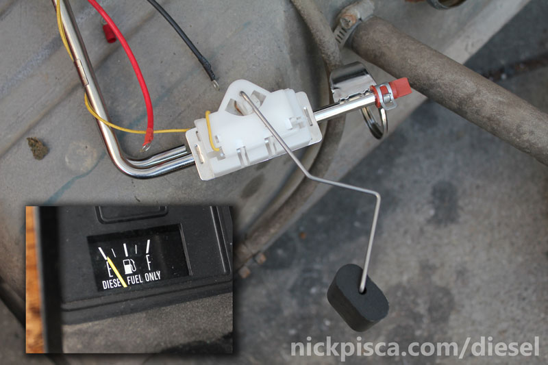
However, I quickly learned that my new sender is not exactly corresponding to “E” and “F.” When mine was at the top, the gauge displayed “F,” however when I got to 1/3 or less, my gauge was already reading below “E.” I can live with a gauge that shows an over-full tank, however I cannot have a gauge that can’t display when my tank is near empty. So I needed to come up with a solution.
Modifying the Sender
I rotated the tank sender float until my gauge read “E” exactly. Then I marked its location with a permanent marker. My plan is to bend the wire so that the float will be located at the bottom of the tank and my wire will stop at this mark. This won’t be easy, because the metal is kind of brittle and can easily break. So use care when bending your sending unit wire.
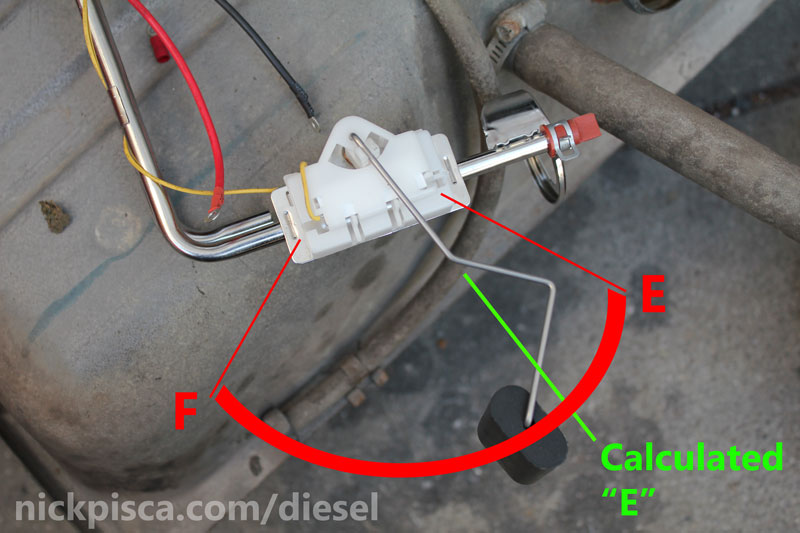
To make sure I bent my sending unit wire properly, I laid it on a piece of cardboard and marked the location of the fuel hose, top plate, and bend in the tubing. Then I used the float to make an arc, denoting the location of the bottom of the tank and top of the tank. Since I want the 1/3 point of the resistor to read “E” on my gauge, then I need to bend the wire so that the float sits on the bottom of the tank but doesn’t allow the resistor to reach the lowest point in the device. That means bending it downward, however, there needs to be a balance of how it is bent so that my top-most location of the float still reads “F” when the tank is near full.
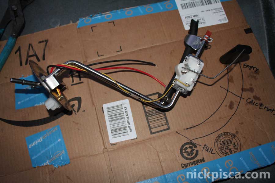
Here is how the sender came out of the box, and here is how I ended up modifying the sender to allow for a new low-reading:
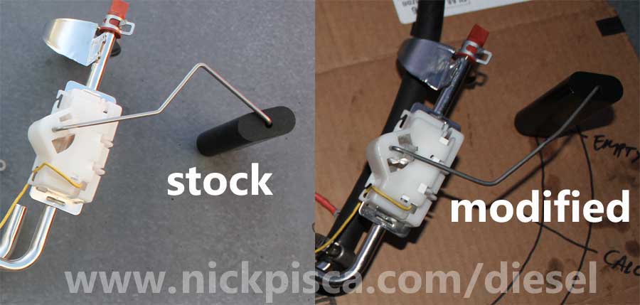
This is a good compromise because it moves the “E” to the right place (at 1/3), while only losing a small proportion of the tank at “F.” Ultimately, I’m not concerned with how accurate the reading is at “F.” It’s irrelevant to me if my tank is at 7/8ths or 3/4ths or 15/16ths. However, it is very important to me to have an accurate tank once I get below 1/4. So this is a good balance of priorities.
Reinstallation.
Once the wire is bent to your liking, recheck your resistance on your gauge. You might have tweeked your resistor by accident by bending your float wire. Then reinstall the new tank gasket (supplied by the Dorman kit) and put the sender assembly back in the tank hole. Look down the fuel nozzle hole to make sure your fuel hose is near the bottom of the tank and that your float is near the bottom as well.
Clip your old diesel fuel sender electrical connector off and splice in some male spade connectors. Remember the ground wire goes to the outermost prod and the non-black wire goes to the 3rd prod in the new sender unit assembly. Connect those spade connectors and cover them with a protective heatshrink or electrical tape.
Install the new tank pickup retainer and rotate it on clockwise. Reinstall your tank, and reinstall the fuel nozzle hoses and fuel return- and supply-lines. Verify all your hoese and connectors are still connected and turn on your IDI van (do not start the engine). If all is well, when you fill the tank with fuel, you should see the gauge increasing. With this particular bend shape of the wire float, you may reach “F” sooner than expected, but that is less of a concern than having no gauge at all.
That’s it. HTH.
No warranty. You are responsible for your vehicle. For novelty use only. Not responsible for anything or anyone. Not responsible for damage to your vehicle, you, or anyone or anything.
Update 5/23/2017: On Ebay, a seller named “stilwellobsolete” recently was selling NOS (New Old Stock) CENTER tank diesel van senders. If in the future they are not selling these highly-sought-after and rare items, the pertinent Ford information is as follows: Part Number: E9UZ-9275-A “Fuel Sender” W/O 094954. I purchased one and will post photos of this unit soon.
Update 1/20/2018: Here is the updated article explaining how to install the aforementioned E9UZ-9275-A Center Tank sender and fuel pickup on the center tank for a 80’s IDI diesel Ford van:
Update 6/5/2018: While discussing the modification of gasser-to-diesel van senders on the OilBurners forum, user Ravdav mentioned some valuable information that could help anyone wanting an alternative to my bending method for doing the sender conversion. Here is his comments about my article:
- “That is an interesting article, but you quit too soon. The bi-metallic gauges have trimmers to set the E and F points. It takes a few iterations because they effect each other.But you first need to adjust the float so that it is almost at the bottom when empty. You can also set the float to be almost at the top when full, but that usually requires altering the length of the float rod.
Image Credit: ravdav of the OB Forum. oilburners.net/members/raydav.3603
Then remove the gauge but provide a way to keep it electrically connected. The two trimmers on the back side are accessible with a number one Philips. Then swing the float full to empty and back. Move the trimmers a very small amount. After a few swings you will get a feel for how to coordinate the two. If you want to be picky, when you think you are done, install the sender, add some fuel, drain the fuel thru the normal outlet, and adjust the gauge to exactly E.
I sometimes drill holes behind the gauge so as to do the final adjustment with everything in place.”
This would have been great information to know when I was converting my sender. But since I already completed it as is, I’ll leave it for now. With the quality of over-seas aftermarket parts are getting poorer and poorer, I’ll likely be replacing my converted sender pickup in a year or two if and when it inevitably fails. Then I’ll write up that process when it happens.
Now that I think about it though, I’m not sure I’ll be able to conduct the gauge modifications without affecting the other fuel tank sender readings. I need the gauge to work exactly the same for both tanks, so adjusting the gauge would mean offsetting the values for the other fuel sender. I’d have to think about this some more, but for others who have a single tank, or are converting both tanks on an IDI Van, they could employ ravdav’s methodology to make sure both senders operate identically. It’s a very useful strategy.
No warranty. You are responsible for your vehicle. For novelty use only. Not responsible for anything or anyone. Not responsible for damage to your vehicle, you, or anyone or anything.
Copyright 2000-2018 Nick Pisca 0001D LLC