
After completing our largest sintering job to date, we had a few things that needed attention. First, the left side tray didn’t rise up. That meant my stepper coupler slipped loose again. Second, while I had the core out of the box, I thought I would try to maximize my z-height capacity by moving my limit switches to the largest possible extension. Lastly, I wanted to tighten down my galvos just in case they wiggled loose again.
Stepper Coupler Fix:
The steppers control the elevation of the trays, and the pulley moving the applicator arm. There are three total steppers in the Sintratec Kit, but only two turn threaded rods allowing for up and down movement of the beds. The threaded rods are secured to the stepper shaft with a “stepper coupler,” which uses small allen bolts to tighten on the shafts.
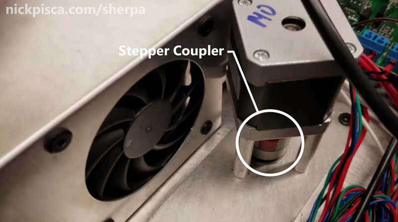
The problem I have is, my coupler is kind of loose. No matter how hard I torque down that allen screw, after a few prints, it decouples and I have to take the core out to try and refasten it. Not the toughest job, but annoying.
I turned the threaded rod with my hands to lower it and inspect the tip. This is a dicey process, because if I bump the bearing and bushing from the hat, it would mean removing the stepper assembly to realign everything. And since the third stepper uses a massive shaft to turn the applicator pulley, that would need to be separated as well. Lots of work.
As I lowered the shaft, it seems a bit loose, so 3D Chimera suggested I try some aluminum tap to shim the gap. I had plenty left over from the shop vac project, so I snipped off something like a 7/16″ x 3/16″ size piece of tape and carefully wrapped the tip.

Then I threaded the rod back up through the bearing and stepper coupler, in the hopes that my tape wouldn’t slip off into the hat or bearing, causing me to have to remove the stepper assembly.
Sadly, due to the closeness of all things, I couldn’t even use a mirror to confirm that the tape didn’t slip off. It’s just very tight quarters.
I had to just wiggle and spin the shaft from below the hat and hope that it aligned with the coupler. As it reached the top, it resisted the threading and that made me think it was as far in as the threaded rod could go. I tightened it down and tried rotating the threaded rod and the coupler in different directions, to verify if the couple was fixed with the shaft. It worked.
Here’s a video of that process, along with the two other mods as well:
Maximizing Z-Height Capacity On a Sintratec Kit:
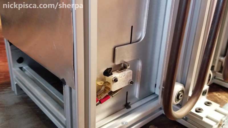
The video explains this a lot better, but here are a few photos detailing this process. Basically, the computer uses “limit switches” to indicate the end of a process. If you are raising and lowering the bed, the limit switch stops the computer from continuously sending steps to the stepper motor and causing your machine to fail.
The further apart your limit switches are, the larger volume you can print. So by optimizing this location of the limit switches in their respective slots, you can eek out a few more millimeters of volume for your builds. The catch is: go too far, and the tray hits the bottom of the core first, and never hits the switch. That’s bad news, and would result in your machine constantly turning and turning and turning until something breaks. So, a clever person can find that sweet spot to gain the largest possible size for his/her printer without destroying the machine.
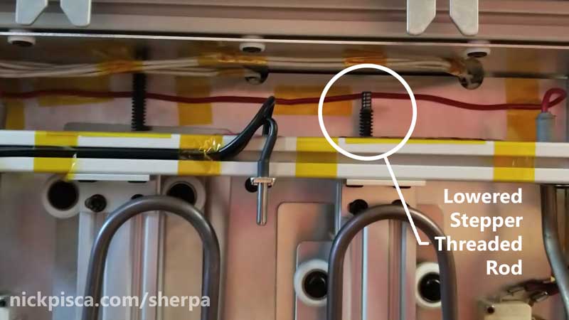
Here’s a picture of the white limit switch engaging as the tray lowered to the bottom:
When I built my kit, I put my limit switches at the very top of the slots, so ensure my tray never hit the bottom. But now that I got only 1040 layers of my potential 1100-layers on Sintratec Central, I’m motivated to move my switches to the lowest possible point. I was able to move mine 2mm lower.
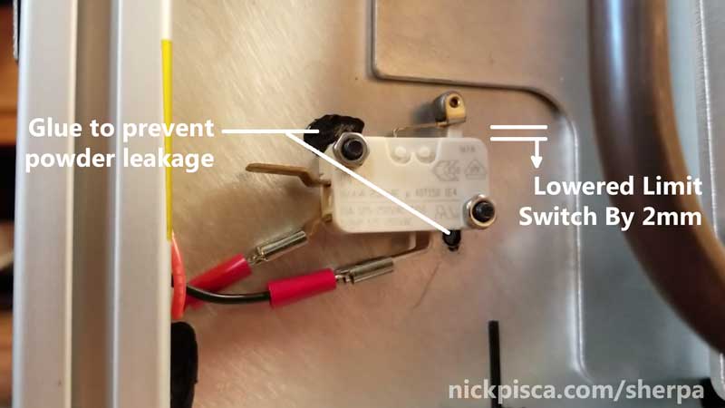
Two millimeters doesn’t seem like much that can constitute about 30 layers. That’s pretty important to me, because that can mean the difference between printing 5 full housings or 6 full housings.
Like I wrote, this is easier to grasp in the video above. Check it out:
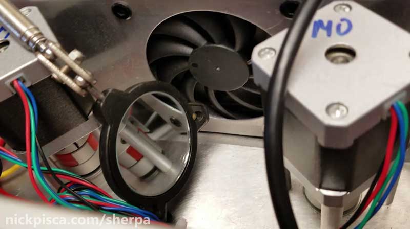
Galvo Fix:
Once again, I had a galvo wiggle loose again. I’ve decided to finally “snug” down those galvos once and for all. I would calibrate the machine and get it to the best possible orientation, and then tighten it to the point where a user cannot just manipulate the drums with their fingers.
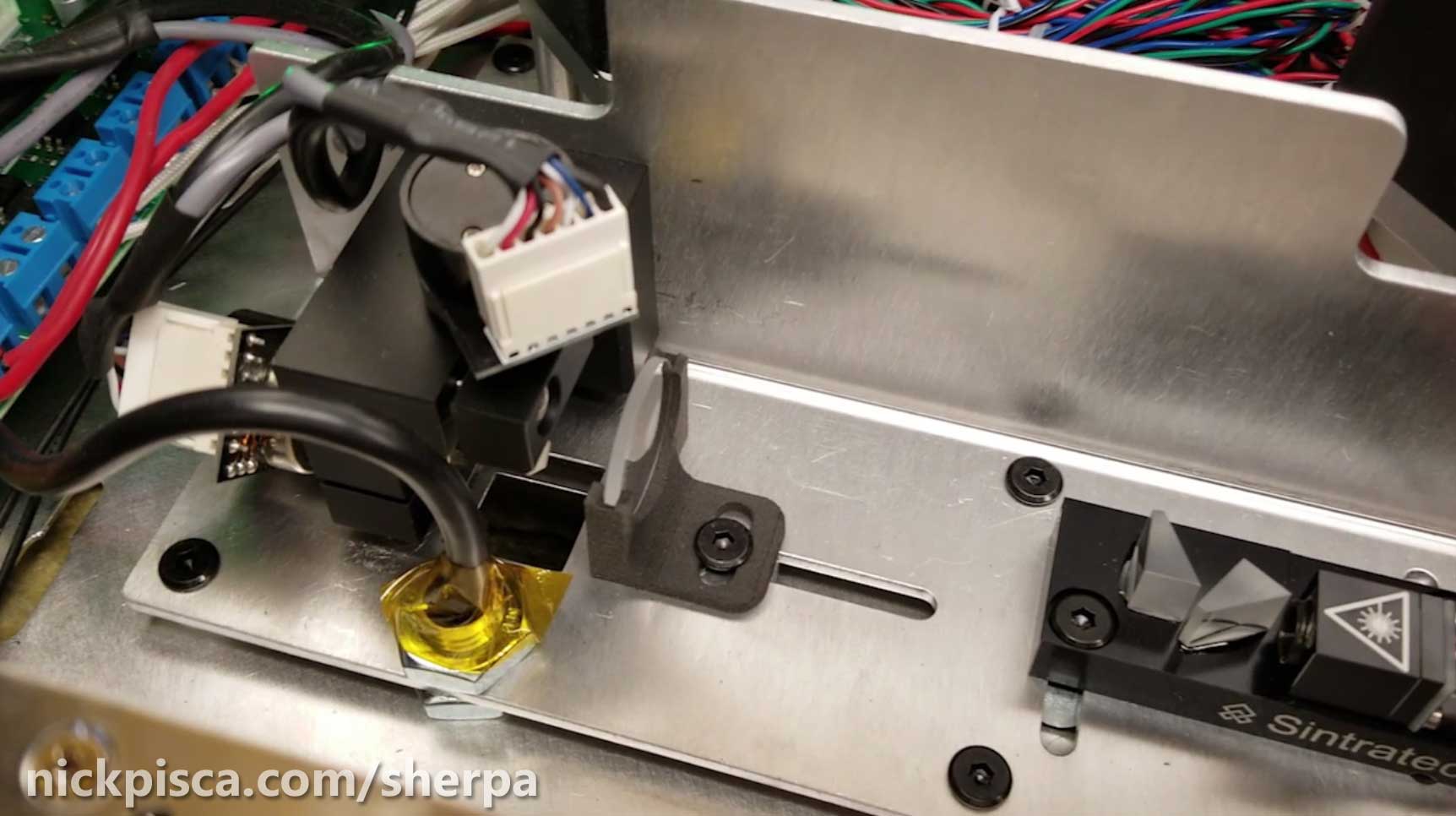
As with any laser project, it is imperative that anyone within range of the laser wear laser protection! I put a lot of that work in the video, but there is more information on the custom tools and process in the previous article, shown below:
Figured Out My Sintratec Hatch Issue: How to Fix the Galvos with a Custom Made Allen Wrench

Recent Comments