The last two days proved to be very productive. Here’s an overview of the accomplished tasks on the Monster:
- X and Y direction axes have pulleys and belts
- All steppers have wire extensions and are connected to two separate controllers
- Both controllers share a power supply and USB (and actually work!)
- Both steppers function independently or together.
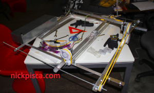
Here’s a picture of the current status of the Monster:
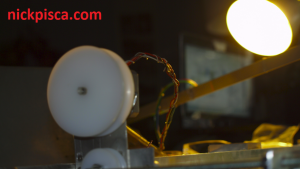
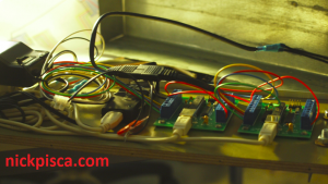
As you can see, there are some yellow round cross-section belts located for their respective axes. Also, the wiring is completed, except for a supporting wire needed for the X-axis stepper. It will eventually support the wiring high enough so that it never conflicts with the tray below it. In the image below, the wiring has enough rigidity to support itself for now, but I can’t rely on this for the long term.
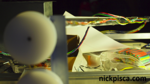
The Y direction stepper has wiring that is fully nestled under the diagonal support brace. The nice thing about the diagonal brace is the middle of the strut is nearly perfectly situated for the arc of movement for the wiring of the X-direction stepper. That was a happy accident.
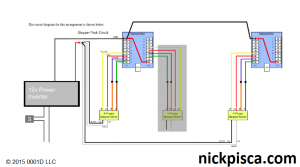
The wiring got a little confusing for a couple reasons, so I drew up a diagram using the base PC Controls diagrams as a foundation. Some of the contributing factors to this diagram was all the wires coalescing at the foot of the control box. There were so many. Also, some of the wires changed colors during my splicing/heat shrinking work. I didn’t have a lot of variety with my supply of 22-guage wire. Orange shifted to blue and brown transitioned to green. After dealing with the crashing of the API’s when the wires messed up in the past, I wanted to make sure all my ducks were in a row.
The beauty of this system is a couple things. One, it allows me to add two more steppers if needed in the future, and I plan to. Two, this maximizes my output count to twelve and my input count to ten. That’s a lot of options! Three, (I’ll get into this more in a follow-up post when I talk about some of the programming I’ve already done) I can use the same command “STP_RunMotor1()” to handle both steppers, simplifying the coding to one method. Then when I add more steppers, these tertiary motors will run on the STP_RunMotor2() method.
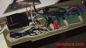
The rats nest of cords quickly became manageable with the diagram. After a few minutes of trimming and plugging, they were all set up:
.
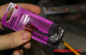
As I mentioned before, I wanted indicator lights on the top of the control box. It seems pretty irresponsible and/or wasteful if a potential user of the Monster accidentally leaves it plugged in all night. I don’t know if my power supply would burn out or not, but regardless, a light would be good to have for that reason and also to indicate the Kill Switch had been used. Luckily, RockAuto had a warehouse sale and I got a handful of these bad boys for just under a buck.
The next section(s) will contain more information regarding the issues I’m having with my pulleys and belts. Also, I will have a section explaining the mathematics I’m using to translate my XYZ coordinates from a 3D application like Rhino/Maya/CATIA into number of steps while coordinating with the other stepper. Like I said, lots got done.


Trackbacks/Pingbacks