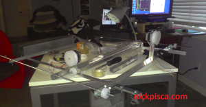
My camera is shot, but a local repair shop says they will take a look at it. In the meantime, I’ll have to post a gritty cell phone shot.
Today was busy. Here are the major bullet points:
- I built a housing for the controllers, hub, and power inverter
- I got the x-axis mechanism to work (yes!)
- I installed the x-axis assembly onto the whole assembly
- I am testing the PC Controls drivers for managing more than one USB controller at once.
That’s a helluva lot for 1.5 days worth of work. Some details:
I was hoping to post a video of the X-axis mechanism working. I was using the AutoStep to put in some short directions to figure out some optimal speeds. Looks like having an interval of 1 ms is too much for the torque on the stepper, so 2 ms intervals are now going to be my lower bound. I’m getting about 1cm/sec speed on my nozzle, which is pretty slow. I might need to go to a friends house who coincidentally has a lathe, so that I can up my pulley size on the stepper, and lighten the weight. Also, I would rather my shafts have a 1/2 inch diameter pulley, so I could translate from a 2:1 ratio to a 10:1 ratio. Five centimeters per second would be right in the sweet spot for my 26″ square CNC monster.
Before I remembered I could have shot a video with my old point-and-shoot, I had already disassembled my controller. I’m basically throwing out the few subroutines I had already written for my controller, because after contacting the supplier, they gave me directions on how to manage more than one controller. The key was to install a basic USB 2.0 hub, then use a different set of libraries (found on their website) that allow for the allocation of controllers via numerals.
Before I got too much into the new libraries, I decided my current strategy of laying my controller on a napkin and having wires everywhere was too risky. I had some trouble recently, when some of my wires disconnected from the controller, and I didn’t see it. That is my fault, because I have been pretty sloppy. To resolve this, I built a housing that has bolted my controller, the 4-way hub, and the power inverter wart to the base. I wanted this, because I thought exposing the hub was dangerous: A future user might not plug everything in right. Also, I wanted to hide the power supply, because it has a switch to adjust the voltage (something I don’t want future users to have access). An added bonus to hiding the wall wart is now the whole Monster can be plugged in with a ten-foot standard AC plug. No more covered neighboring receptacles!
This box has a simple sheet metal cover. It masks all the extraneous USB and power wires. And most importantly, this will allow me to code the monster without risking the controllers and wires with any human interaction.
My insight with the glider wheels proved to be very good. Making slots instead of holes allowed me to adjust the height of the x-axis tray, which was important due to the precise calibration of the shafts. These need to be perfectly aligned or else they don’t spin easily. I found this out the hard way on the x-axis, because the stepper would not rotate. After some synthetic axle grease on the ends of the shaft and down part of the middle, it runs very smoothly as long as it’s aligned well.
The same occurred with the Y-axis shafts, but after some lubrication, things look promising. I need to find a DIY round cross-section belt or band. I was using a simple rubber band on the x-axis stepper, but this probably will not be a viable long-term solution. It was sliding around the pulley, and it did stretch a little. It’s ok for my current mode of testing, but I need it to be more solid for production.
One oversight was the placement of the y-axis stepper. I wanted it to be 8″ above the plane of the Monster, and I assembled an aluminum arm to situate it. However, it twists along the x-axis way too easily. I want to place a 3-foot support strut all the way from the top of the Controller Box, but so far this doesn’t seem ok. (A secondary benefit of this cross strut could be to have a support for the wires to the Y-axis stepper, so I’m trying to figure out a way to do this).
More things on the list are to put a kill switch on the top of the controller box. I want to know if it’s possible to just splice in a simple switch to the positive side of the power supply wire, but do I need to open the circuit on the negative side too? I don’t know enough about AC power to do this. Also, it’d be nice to have some indicator lights on top of the Controller Box to display things like “Power On,” “X Axis On,” “Y Axis On,” “Z Axis On,” “Aux On,” etc.
I plan on wiring up the whole assembly tomorrow, but my heat shrink still didn’t arrive. I’m kind of bummed. Maybe I’ll work on the controller libraries and post the results of my attempts to port everything into C#.net tomorrow. Ideally, if I can get these to work, I can control four steppers simultaneously (X, Y, Z, and Aux axes), with up to twelve separate 12V relays and outputs. This monster will really be something!


![[0001D] Maya MEL Single Polyline Path Image Optimizations](https://www.nickpisca.com/sherpa/wp-content/uploads/2015/03/IMG_9982sfw.jpg)


Trackbacks/Pingbacks