While doing the massive Dana 44 Teardown, I always knew I’d have to swap out the pinion gear to match my rear axle ratio (3.55). These old 1988 Econolines had a lot of different gear ratios, but one of the more fuel-economical options was a 3.55 rear axle. If you have a 4.55 or 4.10, you could haul or tow more, but if you are looking for high mpg and low RPM options, buy a van with a 3.55 ratio.
If you want to determine your van’s gear ratio, just check the axle information on your sticker in your driver’s door jamb. There is an axle code on the sticker, and you can cross reference it with the Axle chart from FTE.
Since I’m retrofitting a Dana 44 front axle on a non-4×4 Econoline Diesel F250 Clubwagon, there isn’t a chart for me to figure out my current pinion gear ratio in the donor Quadravan axle.
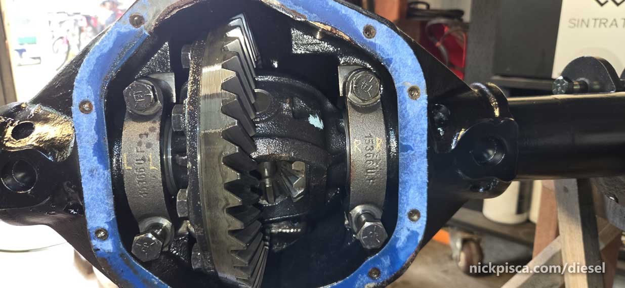
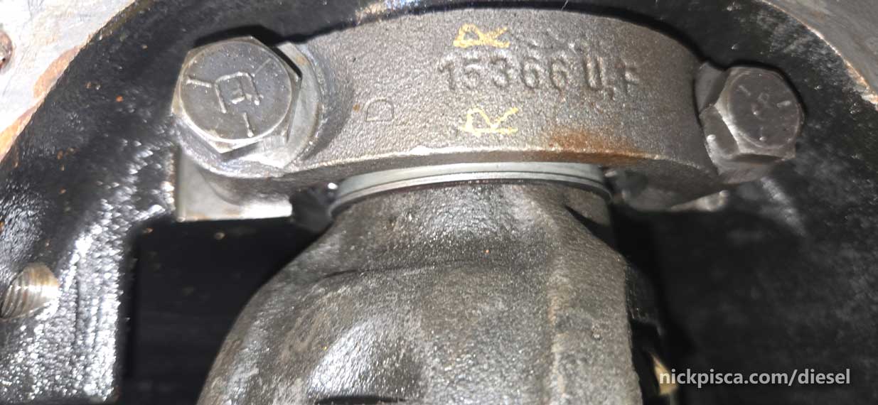
If you read my Teardown article, you learned that I did the crude ratio test when I had the differential housing sealed up. Just turn the yoke and count the rotations of the axle shaft by the rotor. I did that, and I got an approximate count of 4-4.25 turns per rotation, which averages about 4.10. That’s fun and all, but if you want to know the actual axle ratio, you read the numbers on the pinion ring gear. See below: 45 11 1
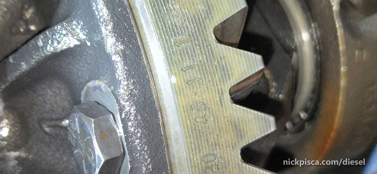
45 divided by 11 equals 4.10.
http://www.southerncaltruckparts.com/
This won’t work on the van. I needed to source a 3.55 pinion ring gear and pinion.
I tried the usual Chinesium Rock Auto garbage, and the expensive Summit online resources, but things were not suitable. Then I found Southern California Truck, Van & 4×4 Parts. Marty worked with me to get everything I needed, and I highly recommend his shop.
Originally, he got me a 3.55 pinion ring and gear, but after I got it home, I researched that Dana 44’s are unique. They have a different carrier for the 3.92 and up. Since my current ratio is a 4.10, I can’t use the 4.10-carrier with my 3.55 ring gear. If you want to see the difference, the mating surface is sunk lower on the smaller ratio ring gear.
Differentials Website shows this really well with this diagram: https://differentials.com/technical-help-2/carrier-breaks/
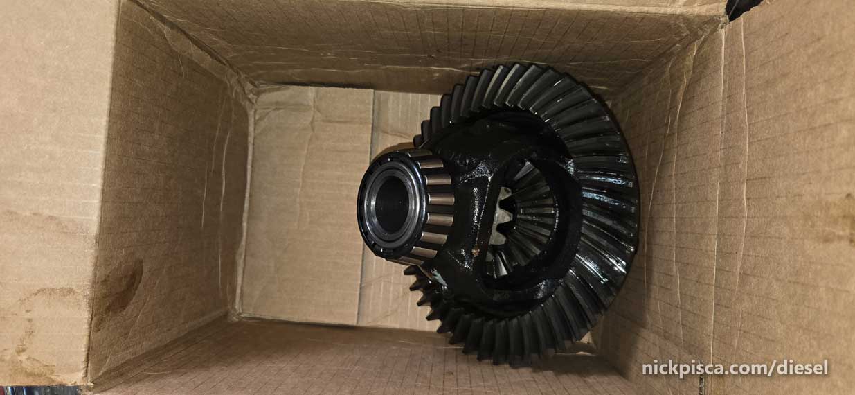
I called Marty up and asked him if he had the carrier in stock as well, and of course, he does. He even said to bring in the current 3.55 ring and gear, and we’ll just swap it for a 3.55 dana on the carrier. We added a small amount for the cost of the carrier, and this even included the spider gears.

All I had to do was clean off the dust and install new bearings. I think these parts were on the shelf for decades. That’s ok, because I’d rather have stock parts, instead of Chinesium. On my way out of the shop, Marty gave me his cheat sheet on how to read differential “patterns.” This was immense help. I didn’t realize just how much I was going to use this.

I drove back to the shop to remove the differential carrier and get started with the new install. Prior to removing the bearing caps, I marked them with “R” and “L” so that I knew which cap was on which side, and which orientation as well.
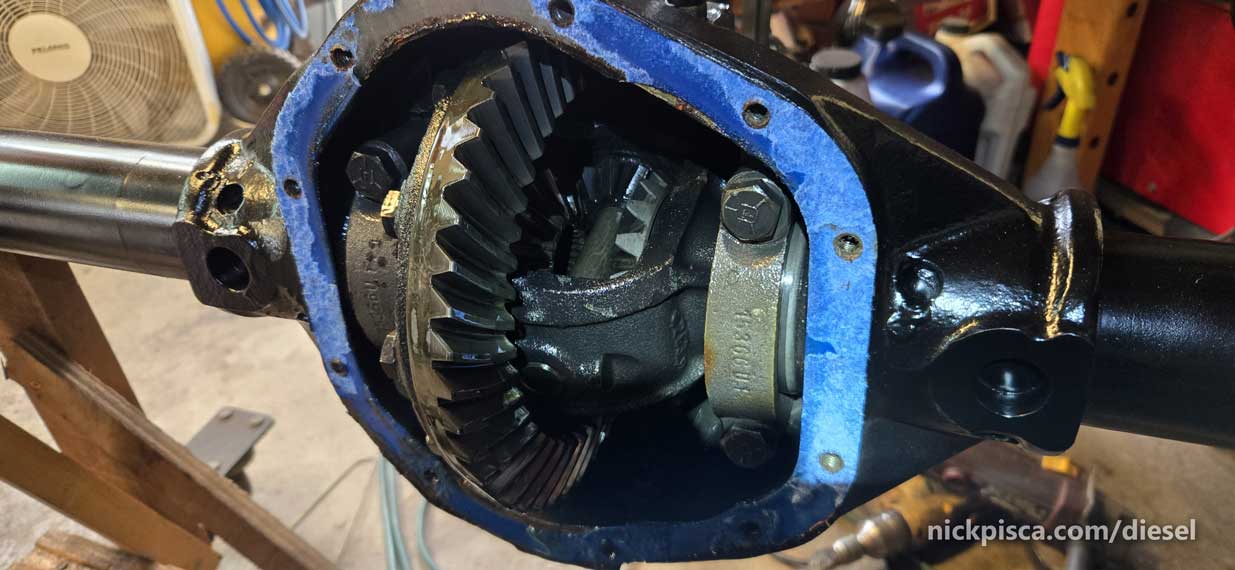
Using a 1/8″ thick piece of aluminum, I used that to extract the differential from the housing. Wedge it in the carrier opening near the spider gears, and turn the yoke. It’ll rotate and pry out the differential. Aluminum is a good tool, because it can’t scratch or ding your steel.
Empty diff housing.

While everything was apart, I popped out the axle shaft seals, but I’ll post a small article about that on a different day. I just want to focus on Diff swap here.
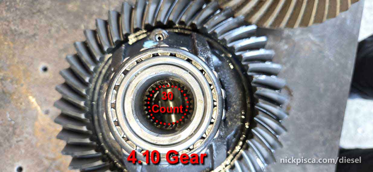
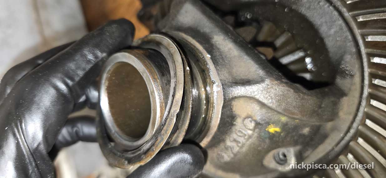
First, let’s very that the axle shaft spline count is the same. My 4.10 is a 30-count.
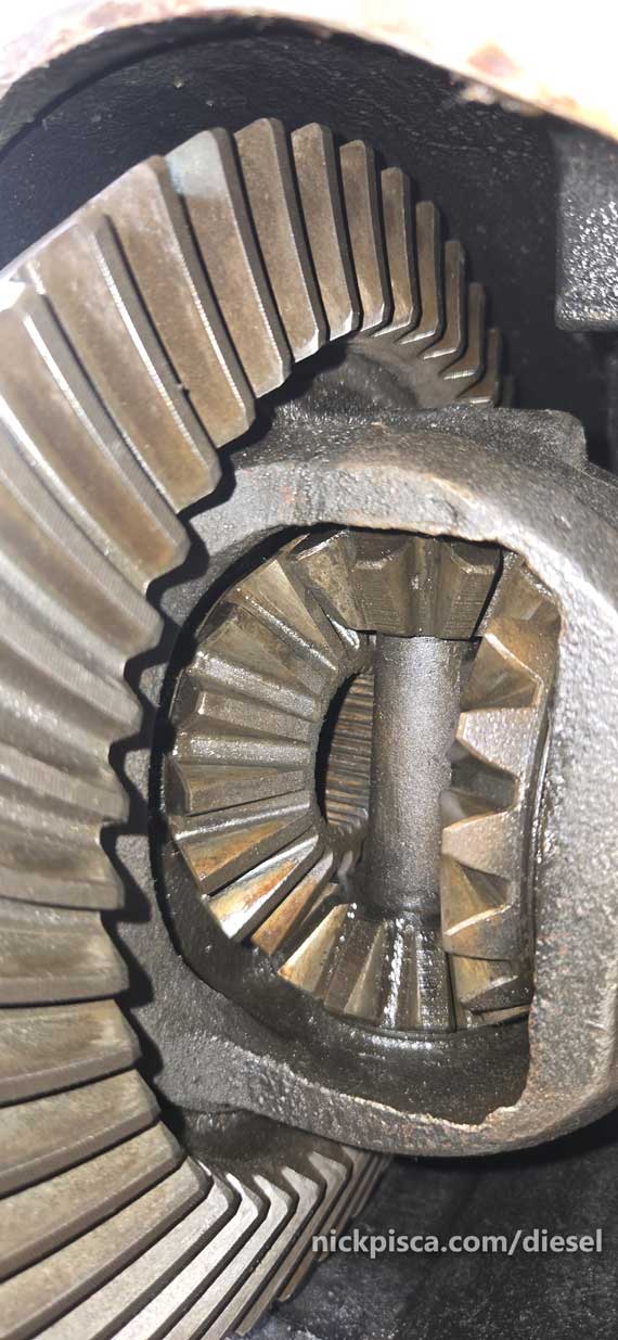
Let’s check this dusty 3.55 carrier and see what we got.
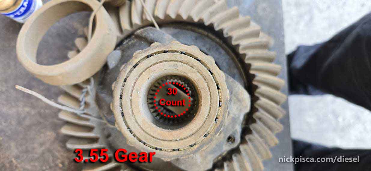
This worked way better than Harbor Freight.
That’s good. Another way to check is to slide the axle shaft into the carrier and see if it fits.
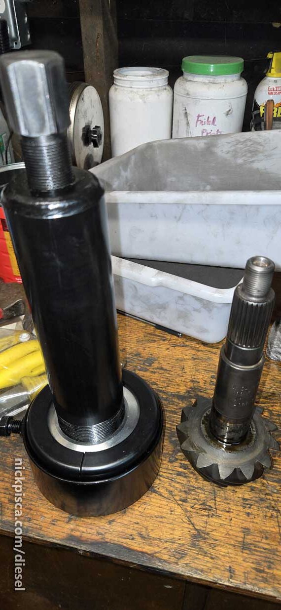
I need to get these trashed bearings off the 3.55 carrier. I bought new ones since these dusty bearings are totally shot.
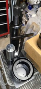
I tried to use a crappy basic Harbor Freight bearing puller, and I basically broke it. Then I ordered another puller from Amazon, and it broke as well. These bearings were VERY fused to the carrier race. Ultimately, I broke down and bought a Cadillac type bearing extractor that is supposed to work on the most stubborn bearings. Bestool Carrier & Pinion Bearing Puller.
It’s a clamshell style puller that uses concentric extraction to minimize damage to the bearing.
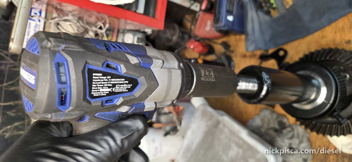
Then use a impact driver (or socket wrench, if you are a masochist) to ratchet the top threaded rod to extract the bearing.
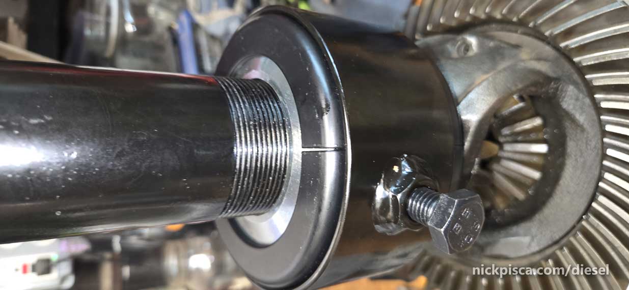
The clamshell just barely fits around the bearing shims on the carrier.
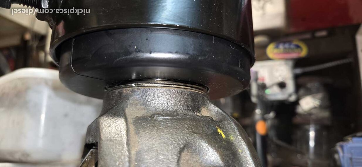
Well, after 5 minutes of hammering destroying my ears, I came to my senses and put in some ear plugs. It’s going to take a long time of ratcheting to get these old bearings off. Wear ear protection.
It’s almost off.
Success! That was loud. The bearing is in the clamshell. (NOTE, install the bearing race on top of the bearing when using the clamshell extractor. It’ll protect the bearing.)
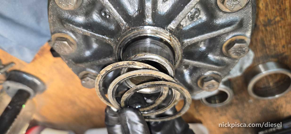
I saved all my shims in the order they were installed, just in case I needed to use them again. I know that they won’t work in the new diff housing, but I keep everything documented regardless. I’ll use the same spacer distance as a starting point for the pinion ring pattern.
Flip over the carrier, and do the same with the other side bearing extraction.
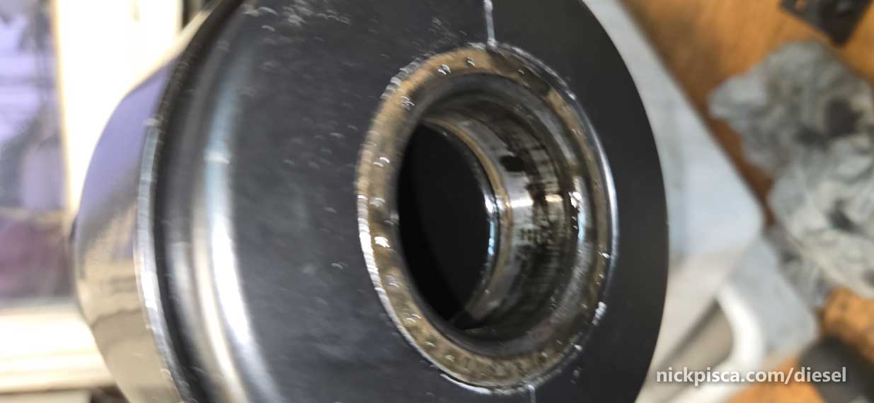
Time to pull the old bearing off the pinion as well. I don’t have as many photos, but it’s basically the same thing. There are no bearing shims on the pinion because the shims go behind the inner bearing race, which I’ll go over later in this thread.
More information to come, just need a break from writing.
Update 2/4/26.
That article shows how I installed the two side Axle Shaft Seals, and why not everything RockAuto and YouTube is correct. Also, the pinion seal was a fun job after spending a few hours breaking my tools trying to get the pinion nut off.
Reassembling the Carrier and Pinion gear!!!
I’m going to take the new 3.55 carrier from Southern California 4×4 and look at the shims. There were about 40 thousandths on the left side, and about 50 thousandths on the right. This ultimately doesn’t matter, because the housing and the carrier came from different differentials, but I’ll start here since it’s better than guessing.
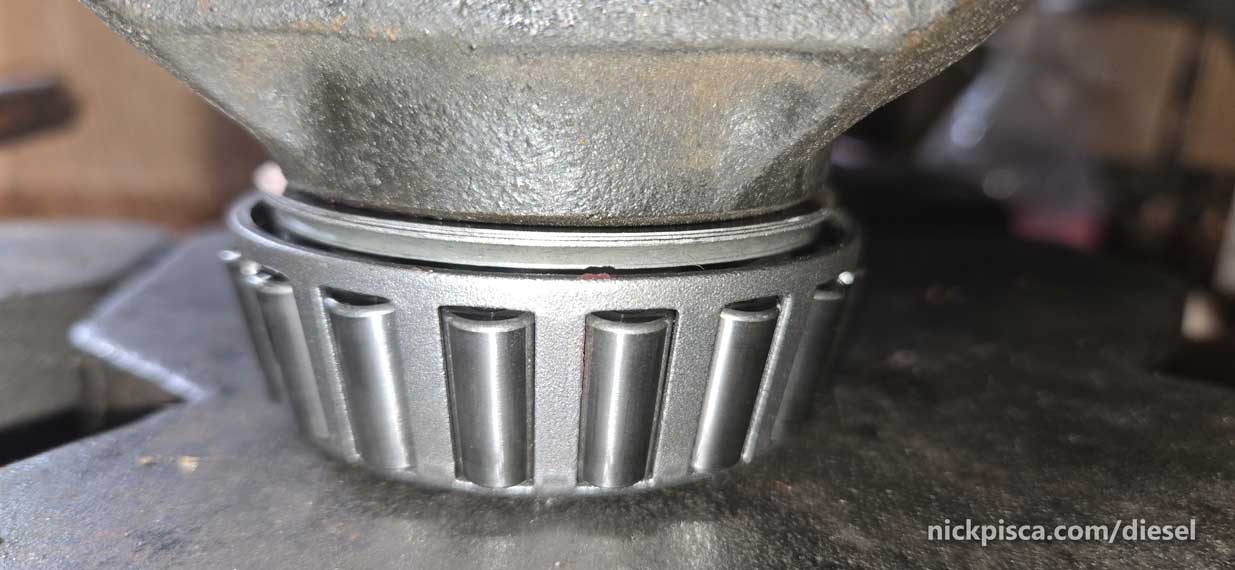
Using my 20-ton press, I smooshed the new bearing on the 355 carrier. You can see the array of new shims on the underside of the bearing. This is the “left” side.

Using the same press, here is the right side of shims (approx 50 thousandths)
This looks nice and all, but I spent about two days taking these bearings off and on trying various shim combinations. That will become more apparent during the paint pattern part of the process.
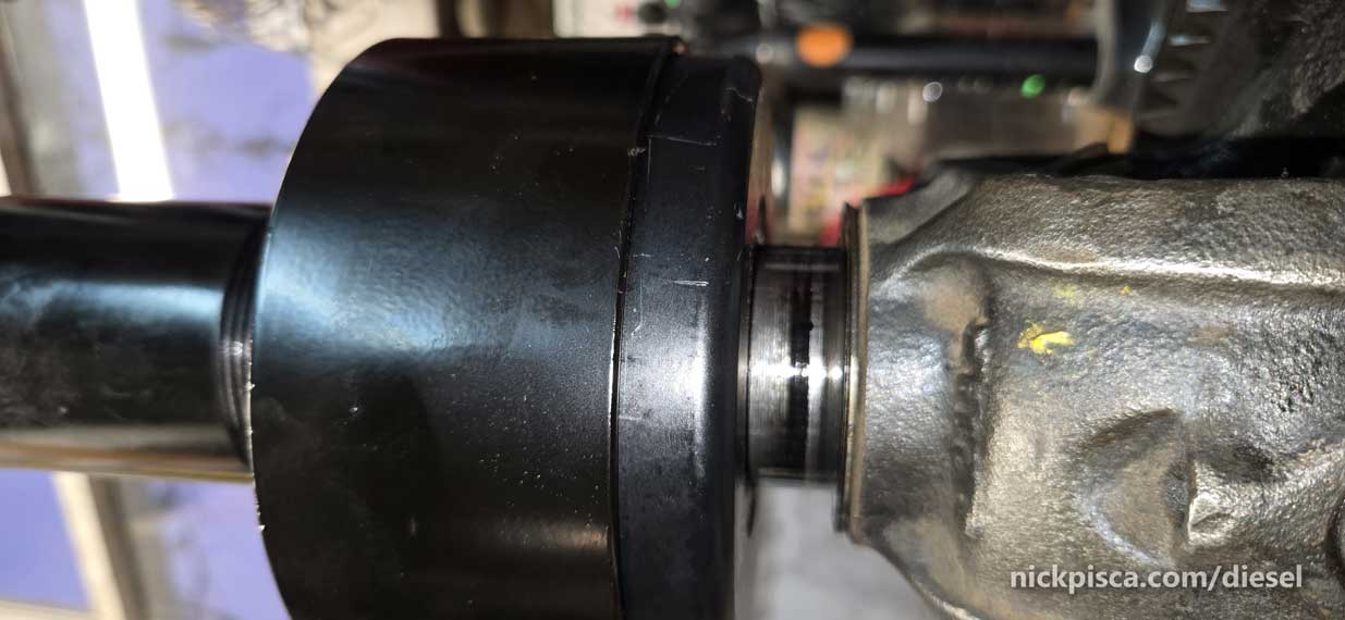
I installed the pinion gear with the proper shims between the inner and outer pinion bearings, so that there wasn’t any axial play, and tightened down the pinion nut:
This is another fruitless exercise, because the 355 pinion gear came from a different housing, so the axial location (toward the front or toward the back) is still not determined until there is a pattern. The shims for the pinion shaft are located in two places (the small shims that determine the inner and outer bearing distance) and the wider shims control the distance from the pinion gear toward the ring gear (front-to-back). I’m just using what the 410 axle had as a baseline, but it could (and will) drastically change.
While working the pinion bearing, I ended up breaking it with the cadilacc bearing puller. I was so pisse.d You can see the bearing housing all dinged up.

I had to resort to using the 4.10 bearings from the previous donor truck. Thankfully, it and the race were still in excellent shape.
If you want to install the bearings in the easiest, but slowest way, and guarantee that you don’t break the bearing, use this hot-and-cold method:
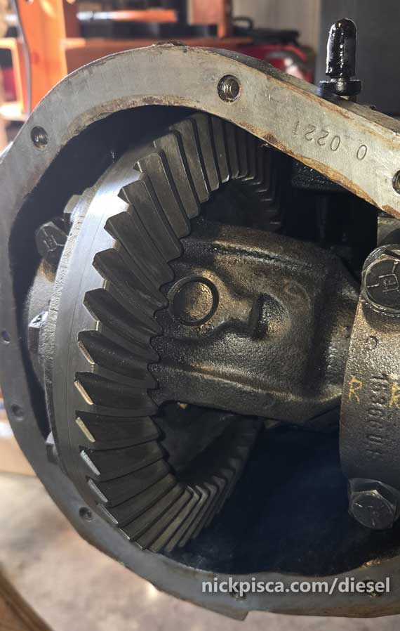
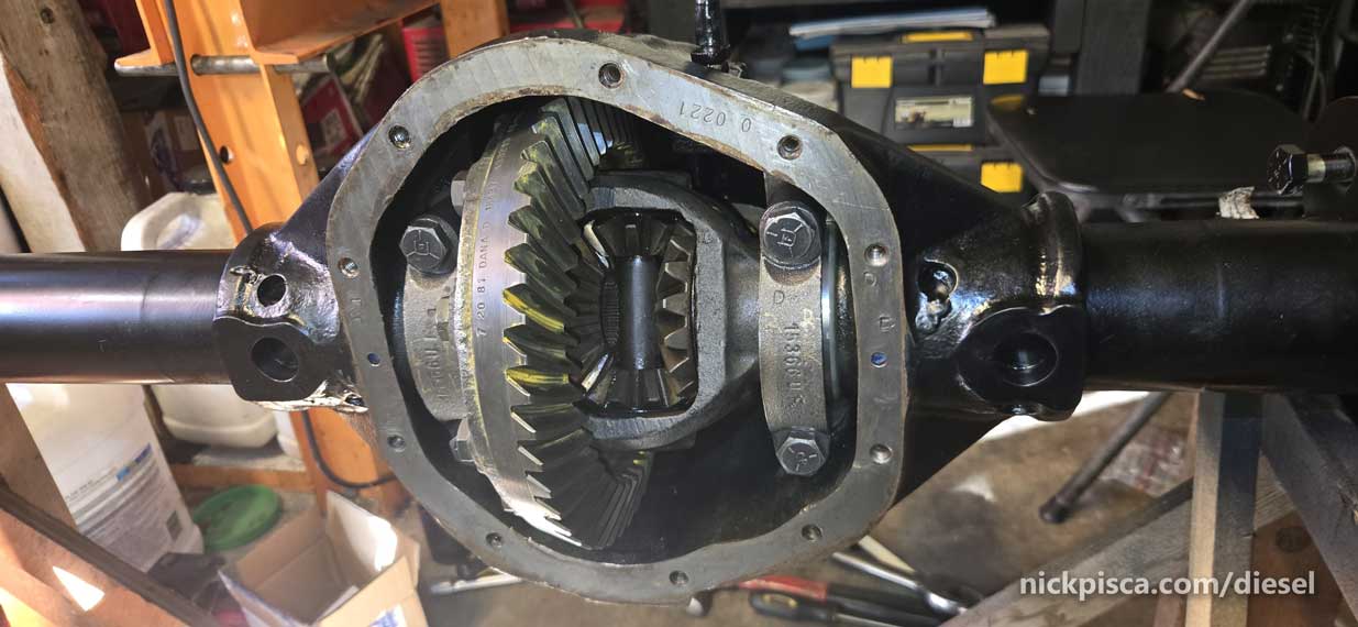
Alright, I installed the pinion gear in the housing and tightened up the pinion nut. Then I slid in the carrier with the 3.55 ring gear.
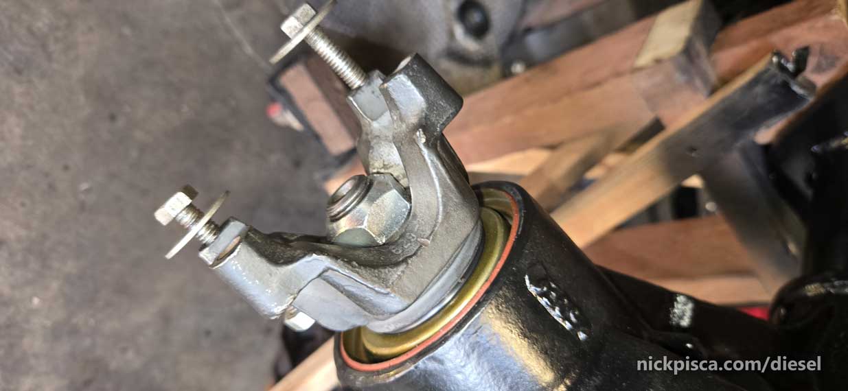
Made sure that my bearing caps were torqued down and on the correct side and orientation as original. Here are the bearing caps and the shims on the right side.
Everything looks good to go for the paint pattern.
Alright, what’s the deal with the paint pattern. Basically, you have to use a thick paint (that should come with your differential rebuild kit) to check the way the gear mesh up.
There are two things to worry about. The paint “pattern” or rubbing. Also, you need to focus on the backlash (the distance between the gears).
Backlash for a Dana 44 should be 6 to 10 thousandths. I used my cylinder bore gauge to measure the backlash. For some idiotic reason, I never photographed that. I set up an aluminum angle on the top of the differential housing. Then I used the cylinder bore guage to set up on a tooth of the ring gear near the middle. Then I wiggled the ring gear to see the difference in bore values. I ended up with ten thousandths, but remember, every time you remove and adjust the carrier shims or the pinion shims, this backlash distance changes all the time. Your instinct is to make it with no backlash, so it feels snug and not play, but that’s not right. You need some space for thermal expansion. If you are snug at room temp, then it’ll bind up at higher temps. Also, too much backlash will have massive play in the rotation of the differential.
The paint pattern was a major PITA though. I ended up taking the carrier bearings off about a dozen times before getting it right.
You gotta start somewhere, so here’s the first gob of paint before rotating the pinion.
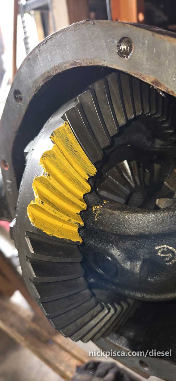
When turning the pinion, put resistance on the carrier so there is a “load.”
Well, this is way too inward (or to the “toe”) of the ring gear. No good. This will wear funny over time.
I removed the carrier, uninstalled the bearings again, and moved the shims around. I had a chart with all my values, but I lost it by the time I started the blog about this. I’m bummed, because it would have been good info for others to learn from.
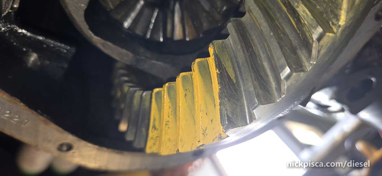
Reinstalled, spun the pinion, and here’s what I got:
Way too inward still on the “drive” and “coast” sides. I’m getting worse.
Removed the carrier, uninstalled the bearings again….
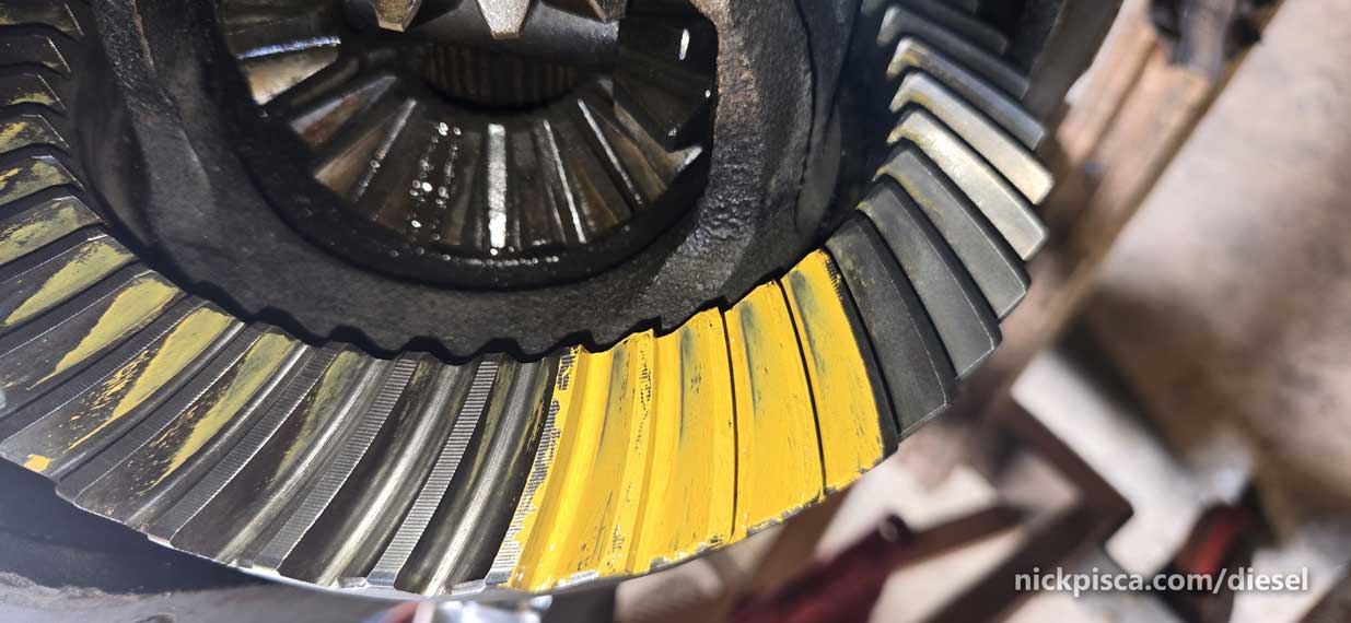
Still too far to the toe, and now it’s dropping into the valley too far, which will be a huge issue. It will cause binding and noise if run this way.
Needs more modifications. More shim replacement on the carrier, but also, I moved some pinion shims (located behind the inner bearing race).
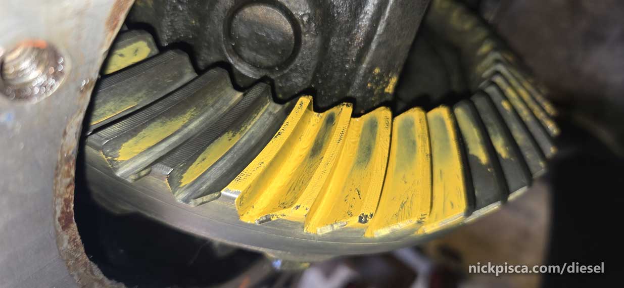

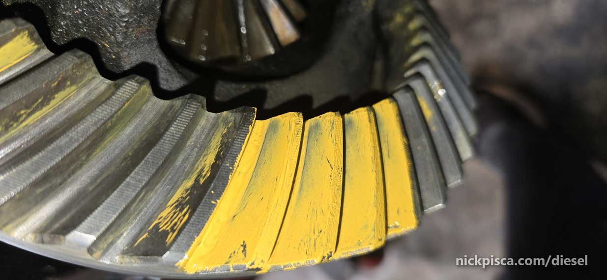
The drive side looks better, but still needs work. The coast side is still close to the toe, but at least I’m getting something that isn’t completely lopsided and out of spec.
I don’t want to bore you with dozens of paint patterns, but take my word for it, but I tried at least another half-dozen combinations, using my cheatsheet from Marty to perfect the pattern.
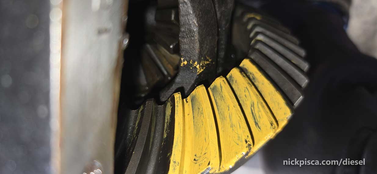
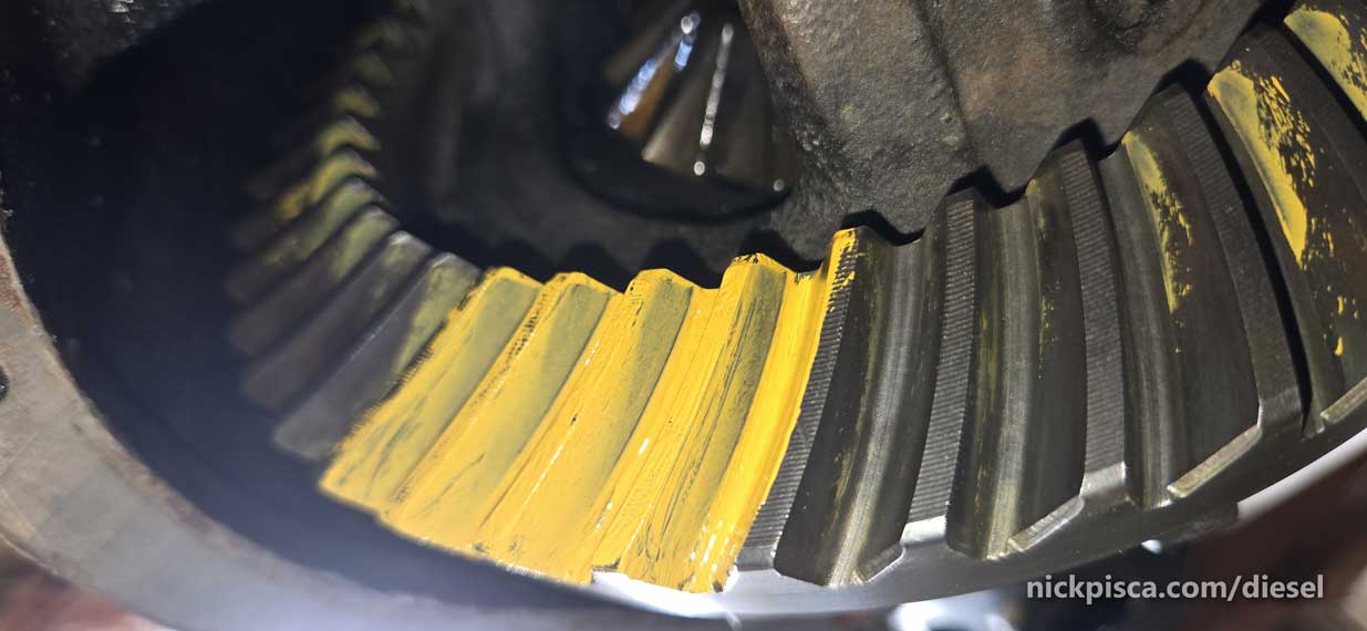
After about a day of installing, painting, rotating, testing, inspecting, uninstalling, new shim alignment, reinstalling, painting, etc etc etc….. I got this result from my 355 carrier, ring gear, and pinion gear setup:
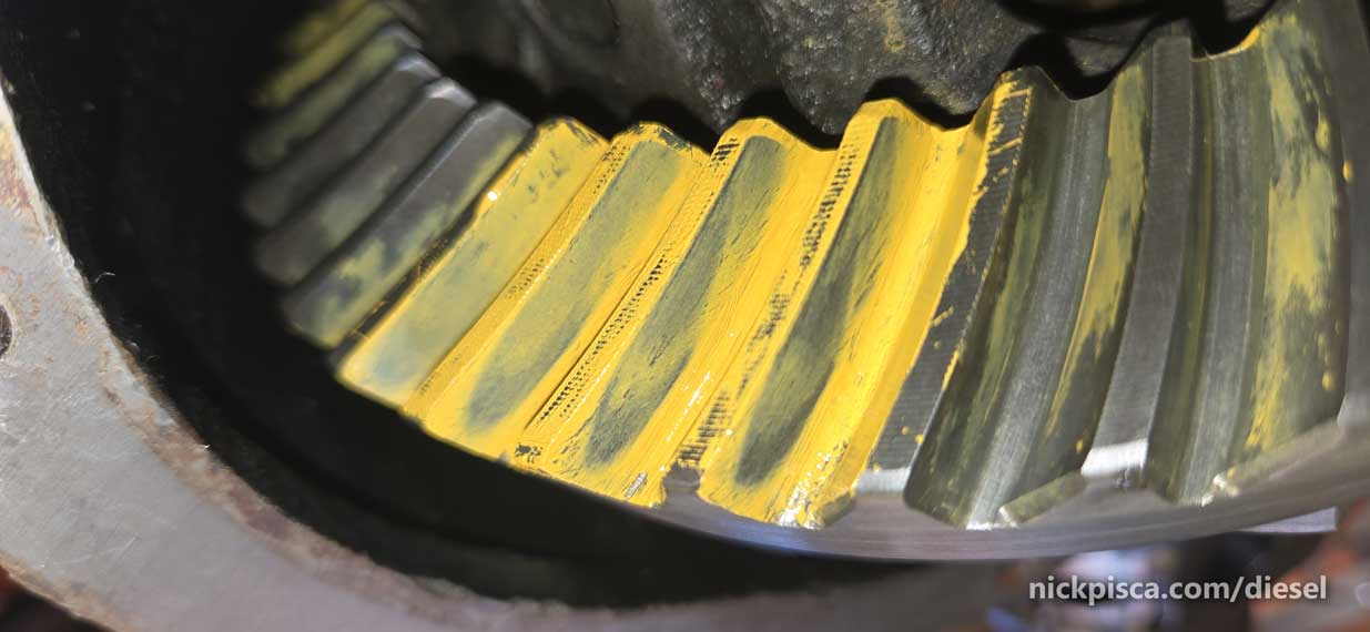
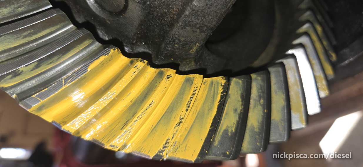
I’m pretty pleased with this. I know it could be fine tuned even more, but I’m going to let this ride considering this is a used 355 set up and I may never get it absolutely perfect. Pick your battles I guess.
I started to clean up the yellow paint and get all the parts back together. I think I got this 3.55 conversion all ready for primetime on the van!
Need to put the diff cover on, fill it with Redline 360 differential fluid, and get it over to the van asap. I’m excited about this one.