Sorry for the delay. Don’t have a lot of time to post updates on the website, but I finally got the trackbar mount in a place that I like. It took a lot of jacking, welding, fitting, cutting, jacking, welding, fitting, cutting… Anyway, I think I’m ok.
Where I left off, I was test fitting the axle under the recent cut to my crossmember.
Naturally, I’m not too keen on these kinds of cuts to the frame, but sacrifices have to be made.
Now, after a few weeks of wrenching and cutting this van apart, and rewatching this old video, I can understand my concern about the proximity to the crossmember. Keep reading, and I learn that the closeness was due to the coil tilting to the passenger side, which you can already see in the video.
You can read more on my post from the previous week on why I cut it at the location I did.
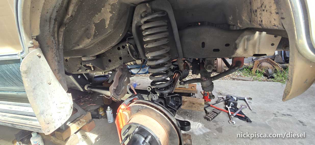
Regardless, I’m moving forward, and I need to figure out how to get this central and not tilting so far. The coils could topple over at any moment.
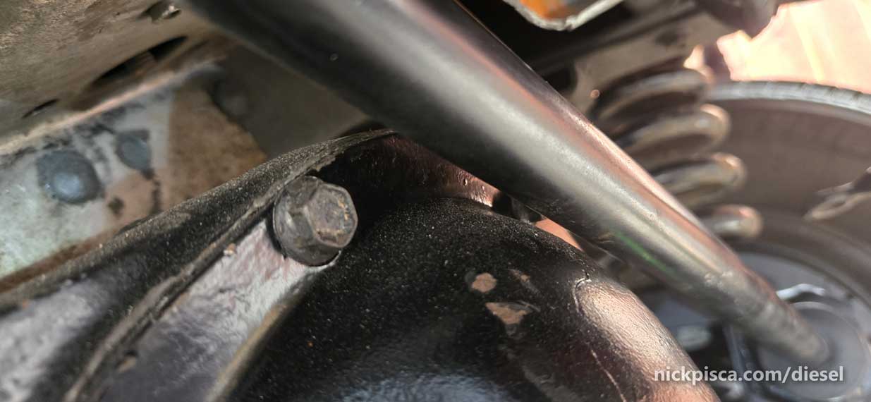
If you remember from a previous post, I had to rethread one of the rad arm holes, due to a busted bolt. Here’s the corner shot, with the bolt still in place so I wouldn’t lose it.
The coil spring bracket goes between the rad arm and the coil.
Coil installed on top of the bracket.
Here’s a closeup. Pathfinder installed some kind of hockey puck looking receiver that gets thru-bolted with a monster 1 1/8″ hex head. 15/16″ nut.
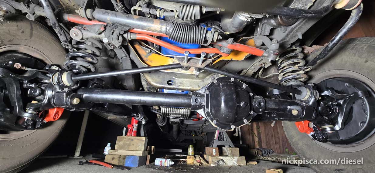
Now it’s time to figure out the trackbar setup. The “Track Bars” according to the pathfinder manual, control the lateral movement, based on a hinge joint mounted at the centerline of the frame. The engine DOES NOT sit at the centerline, so it can take some work to figure it out.
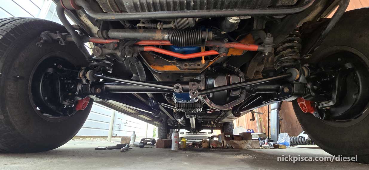
The trackbars are just long shafts with a threaded end at the wheels and the hings at the center. Like wings on a bird.
I need these to be on the centerline, and after some measuring, I found out that it lands exactly at 18 15/16″ from each side of the frame, using the overlapping steel on both sides as a marker for my tape.
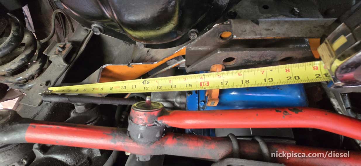
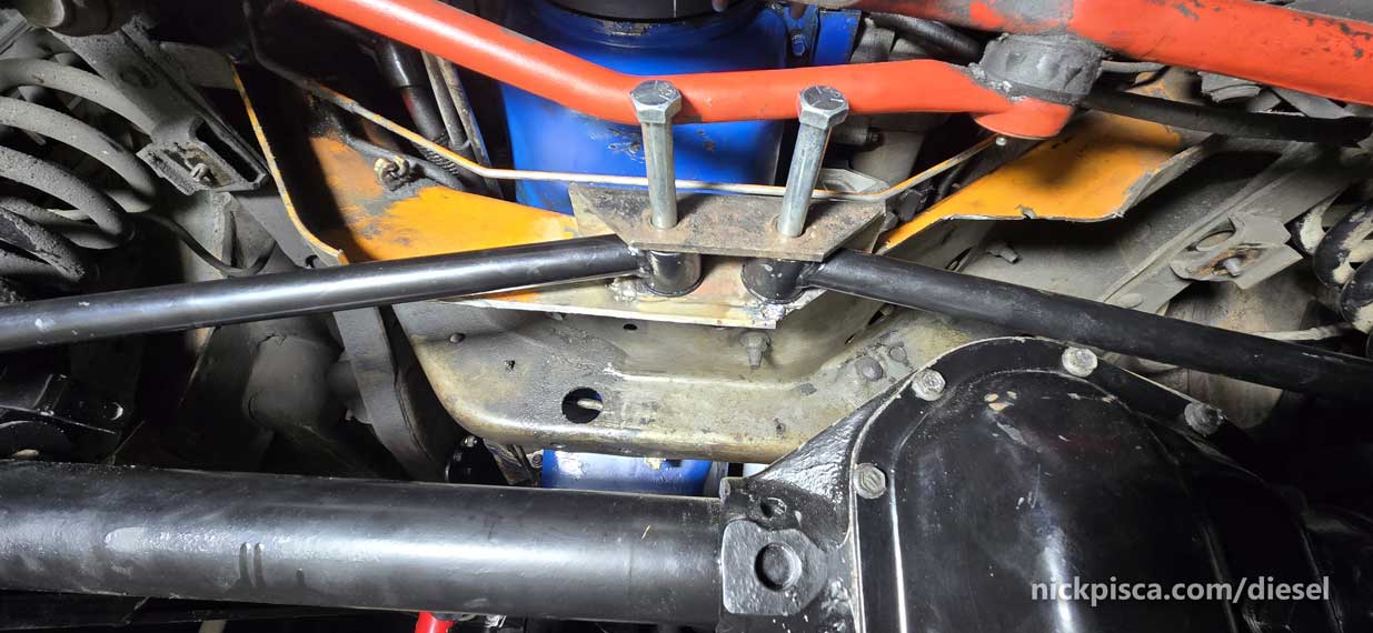
That 18 15/16″ lands at the centerline of the bracket, so I marked that on the frame itself. It was hard because the flange on the crossmember gets in the way.
I am running out of time on this project, so I decided to tack weld that bracket in place at the centerline and hope that it works. If not, It’ll be trivial to grind off the small weld.
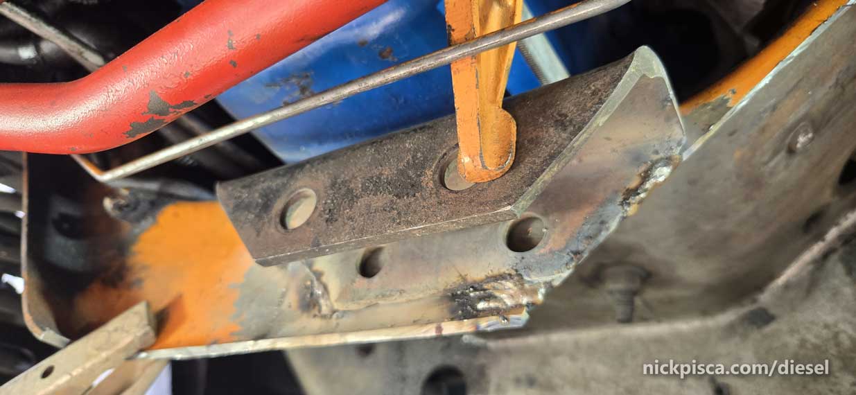
The bracket is really low, but we’ll see how it goes.
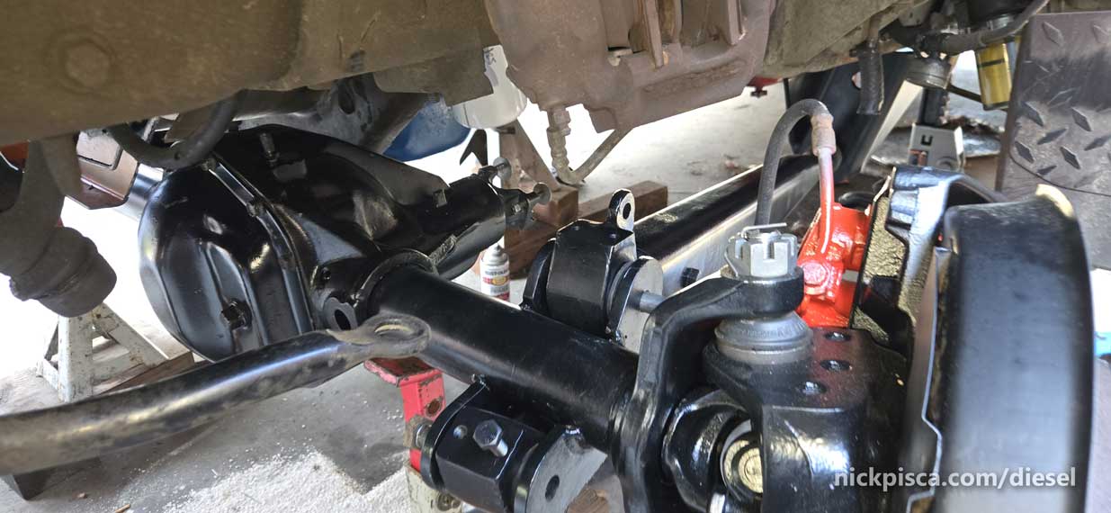
At first glance, it seemed fine. I put those bolts in just to keep the trackbars from moving.
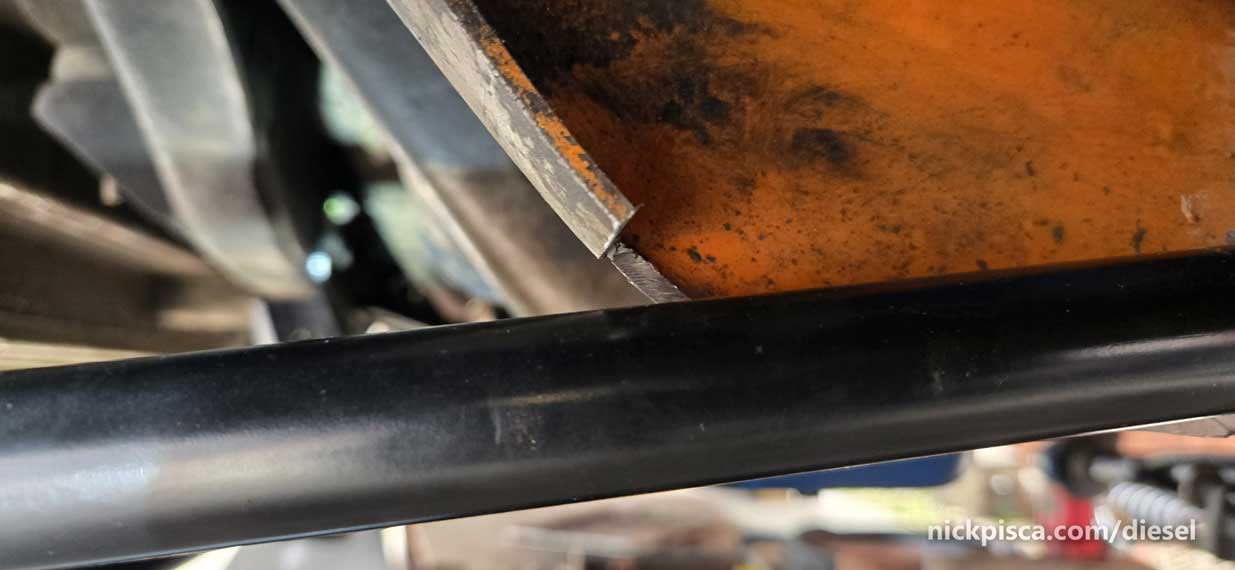
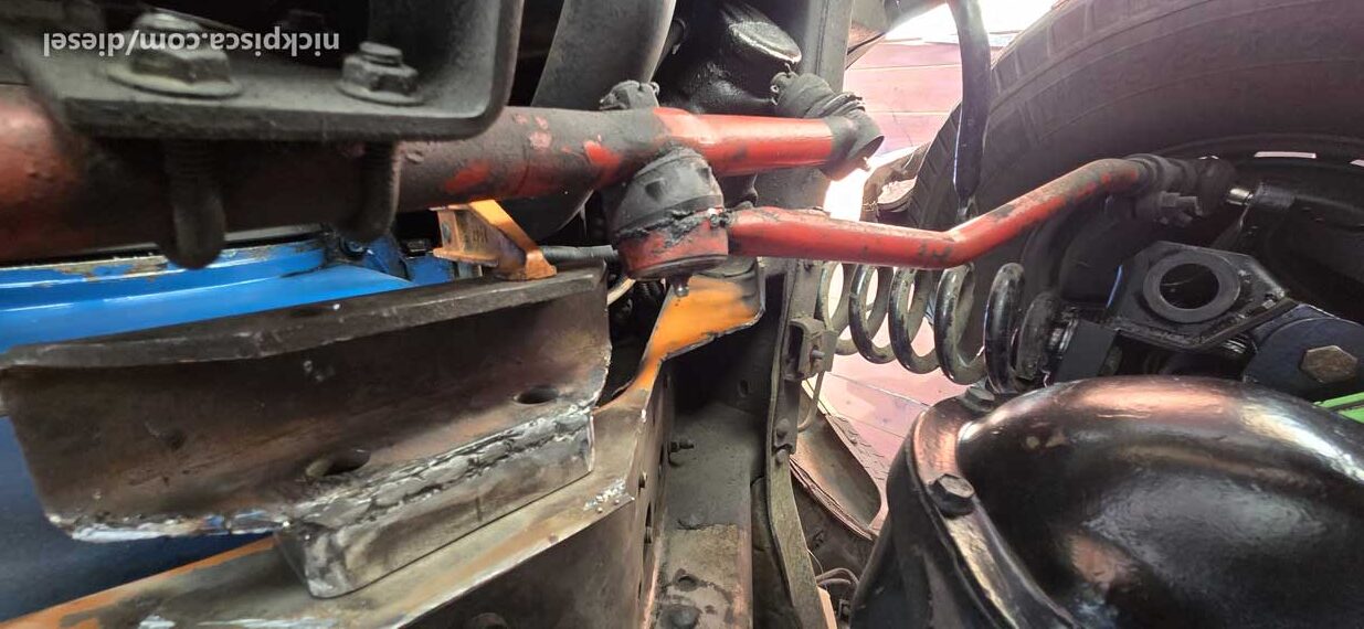
I lowered the van to put the weight on it, and right away, there were problems. The passenger side trackbar is holding up the crossmember. This will need further cuts.
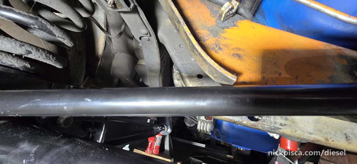
Also, the drivers side trackbar is really tight on the differential.
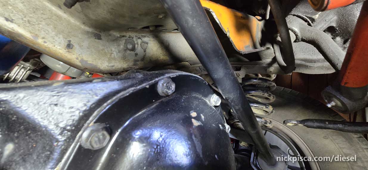
Here’s a quick video of the situation.
More info after introducing some load:
I took the night off and came back the next day with some cuts and movement of the bracket upward.
Even with the new cuts to the crossmember, and the movement of the bracket up, I’m still really tight on clearance.
I needed a new solution. If only there was a way to get the bracket forward more, but keep the integrity.
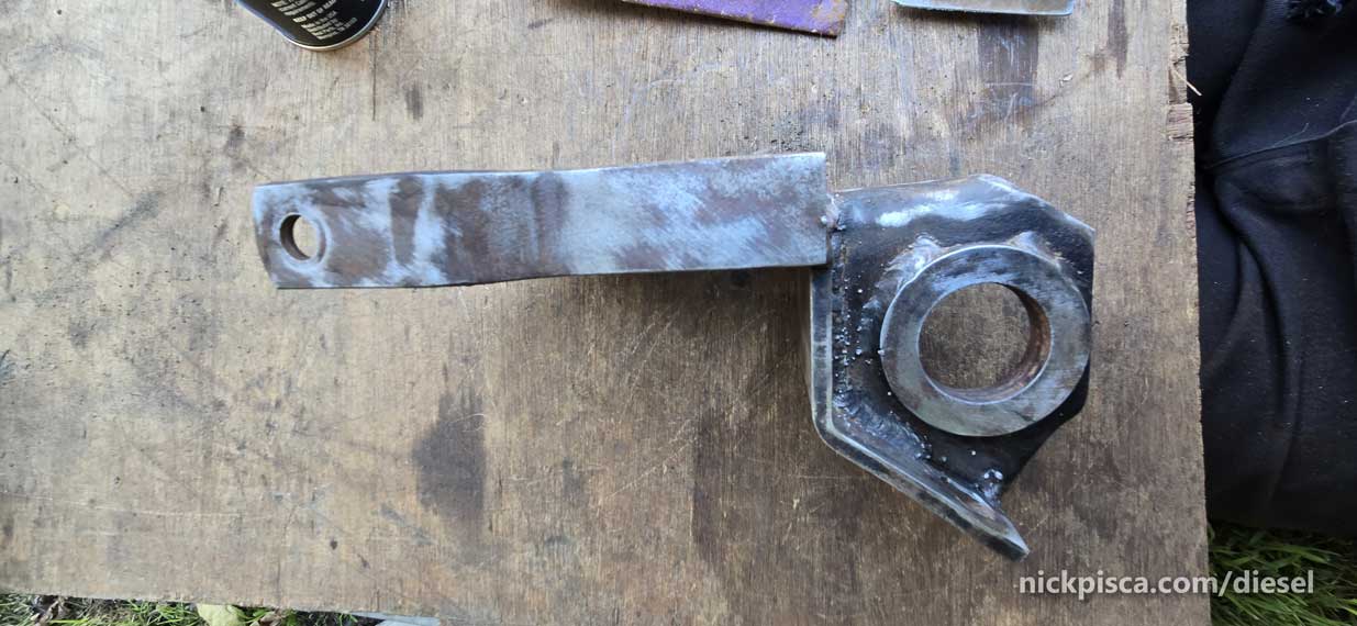
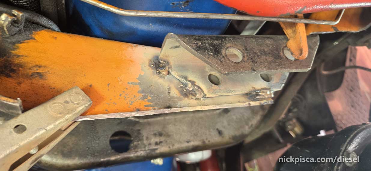
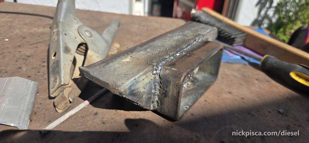
Time to weld an extension tube. (1″ long, cut from a scrap 2″ x 4″ x 3/16″ steel tube.)
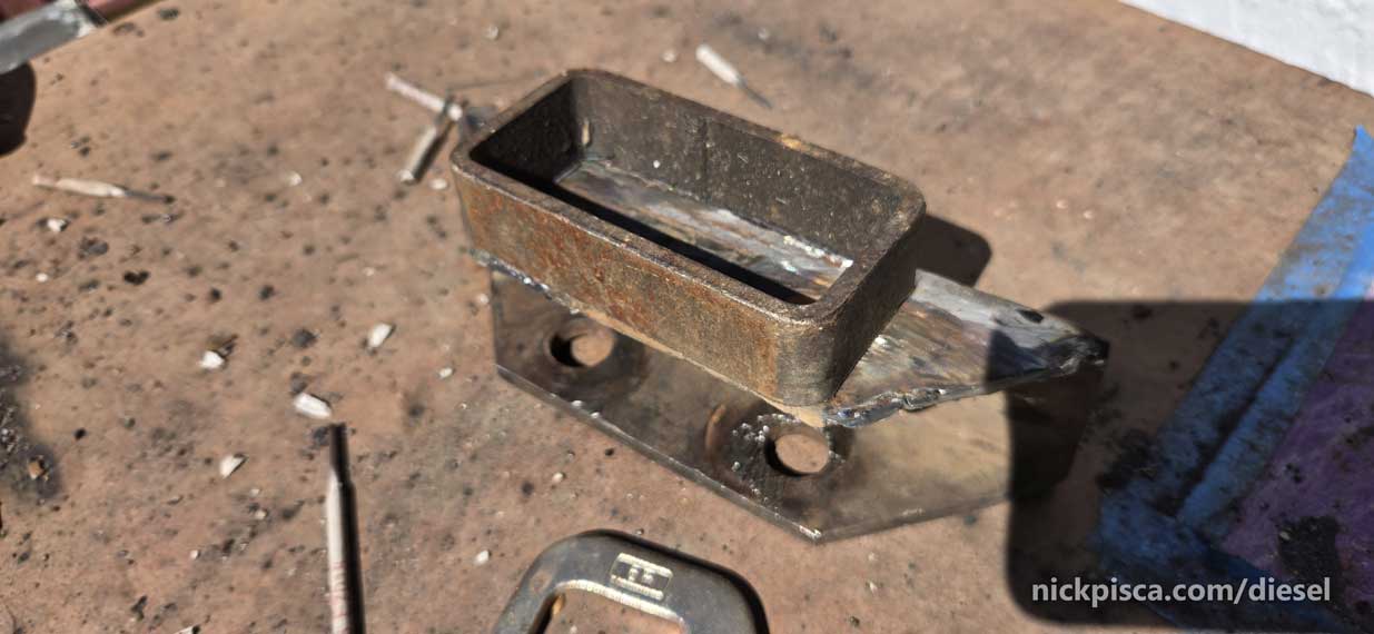
I’ve never stick welded before this project, so it’s been a learning curve. I can MIG weld decent, but I haven’t had access for 2 decades. This stick welder was from a friend who passed away, and I figured I’d honor his legacy with putting that welder to work. I’m getting the hang of it though.
Alright, I tacked it up kind of high, and it’s flush with the top of the crossmember.
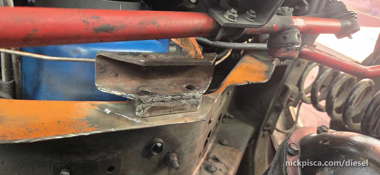
Now I’ve introduced a new issue. Potential conflicts with steering.
Luckily, after rotating the steering all the way to the passenger side, I still have about 3/16″ clearance.
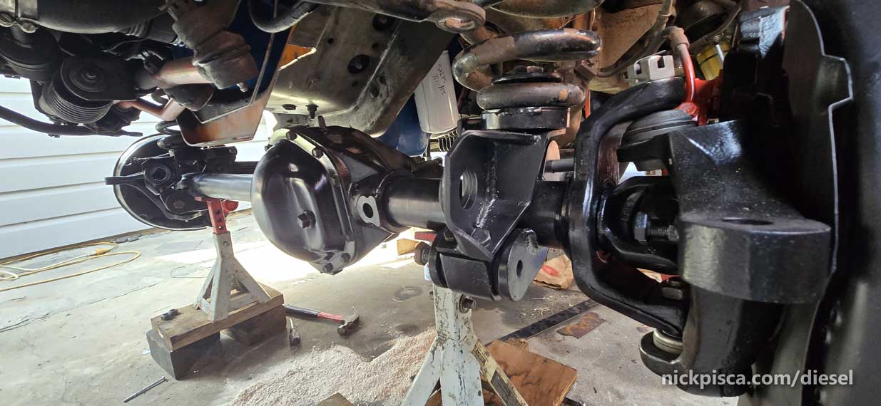
This is looking really decent. Lots more clearance, and things are sort of falling into place.
While I’m at it down here, time to fab up structural reinforcement for the part that I cut out. Some of this 1/4″ steel (1 1/4″ width) should do the trick. It’s way thicker than the original steel that looked like 1/8″ formed steel.
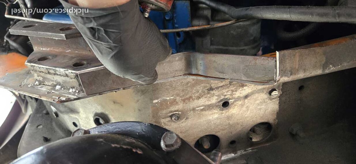
I’m pretty decent at welding from the top or on the side, but underside is a trip.
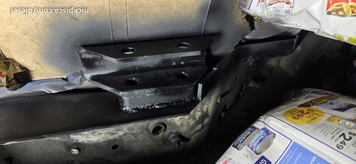
I’m hoping this will hold. The welds for the bracket and extension look really solid.
Let’s get this van a rocking.
Seems to be ok.
Next steps are welding up some bump stop extensions see if we can get this a little safer. It’d be nice to know that this won’t bottom out.
One thing that is giving me a lot more clearance than Boomer’s van is the fact that I used RV coils, which appear to give me a lot of room. Not sure how that will pan out as the van settles, but for now, it’s looking promising.
Need to get this on the road by Wednesday. Next up are brakes, steering, and reinstalling the veg tank. Reinstall all the hoses. Looking like a test drive, hopefully soon.