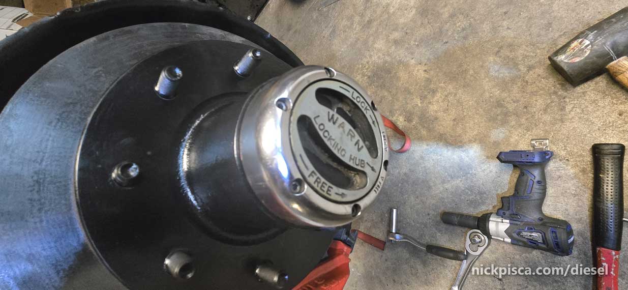
Wanna take apart the Lockout Hub on a Dana 44 front axle? Here’s what lies in the rotor assembly.
These lockouts are not cheap. You can find them online for hundreds of dollars, but even economical places like RockAuto lists them as much as $100.
Removing the lockout assy will allow you to access the spindle nut, which retains the rotor and bearings on the axle.
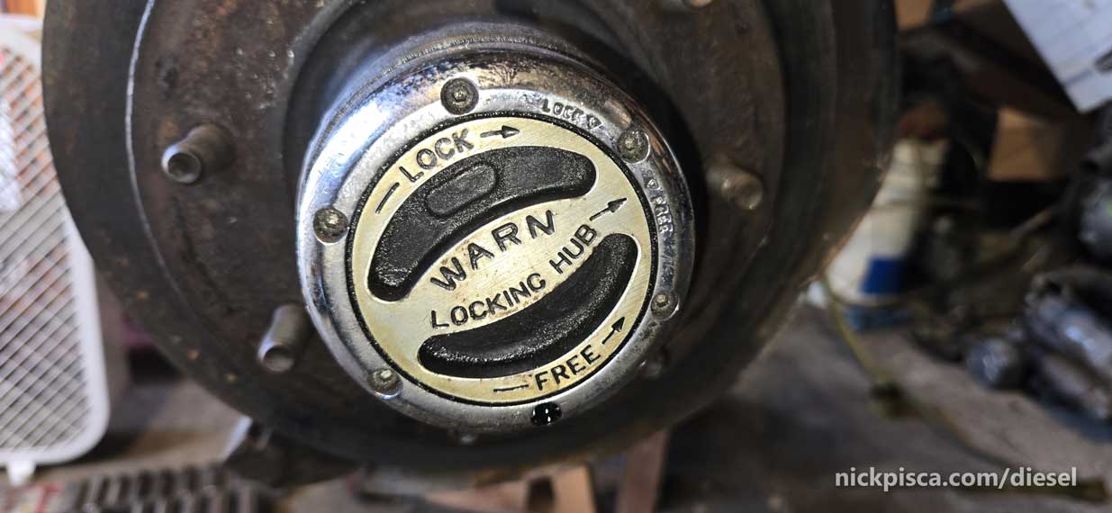
Lockout hubs have six Allen bolts that secure to the inner assembly.
These Allen bolts are 6-32 thread, 1.75″ length. Warn – Hub Fastener Kit P/N 34595
The chrome exterior slides out of the rotor.
Once the exterior is gone, you can see the inside. There are two retaining clips (an outer and inner) that keep it in place.
Carefully with a dental pick, you can pull out the outer retainer.

Next, use a clip pliars and remove the inner clip.
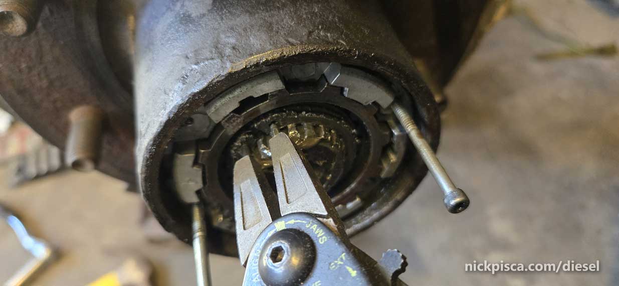
Why did I thread in two allen bolts? Once the retaining clips are gone, you can use the two bolts to slide the lockout out.
Once that’s done, you have the lockout parts out.
Big thanks to Yoshimoshi on the drum brake version, but it’s basically the same thing for rotors.
I slid off the rotor. Careful, the outer bearing might fall out of the rotor.
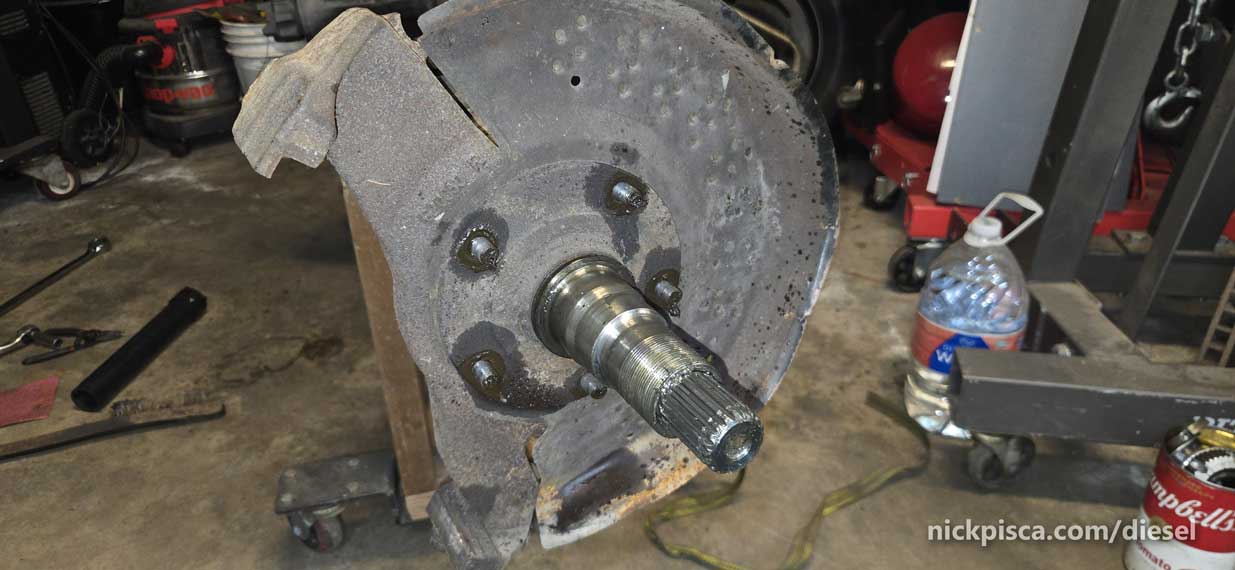
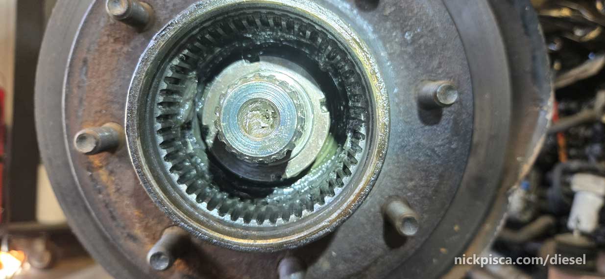
What does the Lockout mechanism look like? Here’s it placed on the axle shaft on the end of the spindle. I’ve removed the rotor to show more of the geometry.
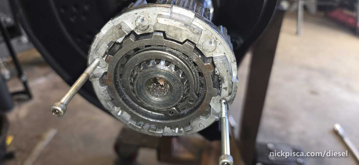
How does it work? When you turn the lockout switch, the mechanism transfers the rotational motion from the axle shaft to the rotor assembly. That allows the wheels to rotate in unison with the axle.
Here’s what the axle shaft looks like inside the spindle. The spindle is fixed on the knuckle. The axle shaft spins concentrically.
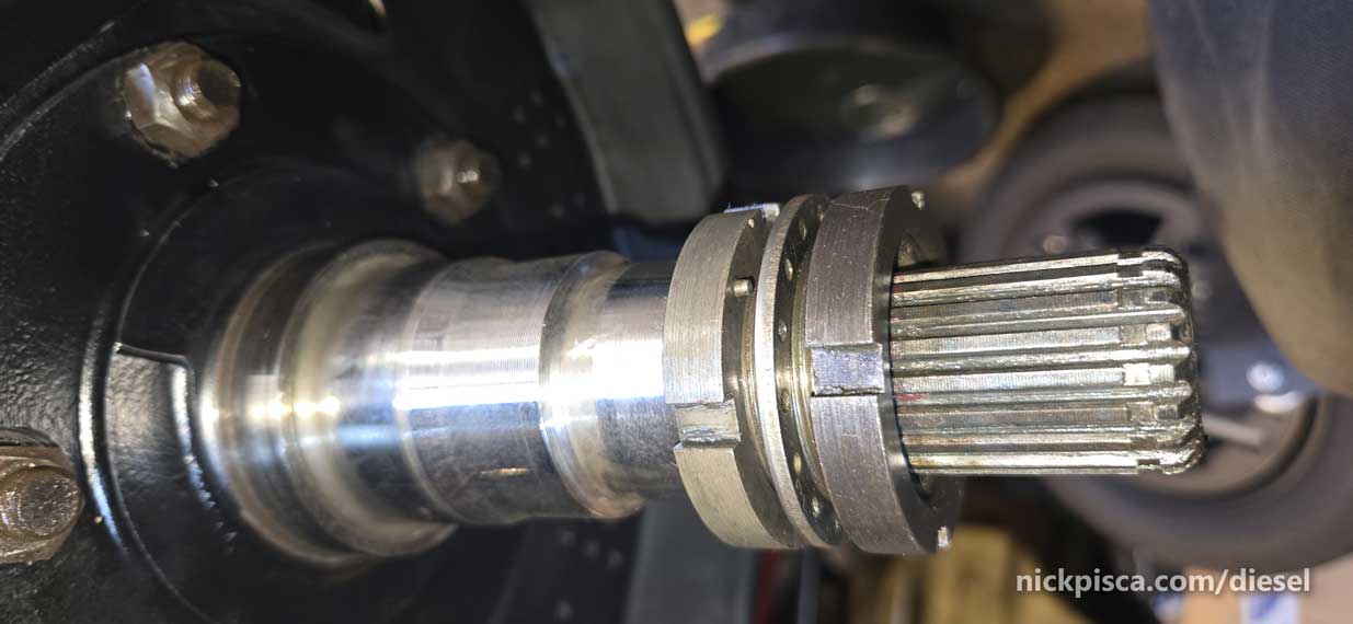
Until the lockout is engaged, the axle shaft will rotate away and away and away without transmitting any rotational velocity to the wheel.
The lockout hub just slides on the end of the axle shaft splines. IIRC, these are 35-spline axle shafts.
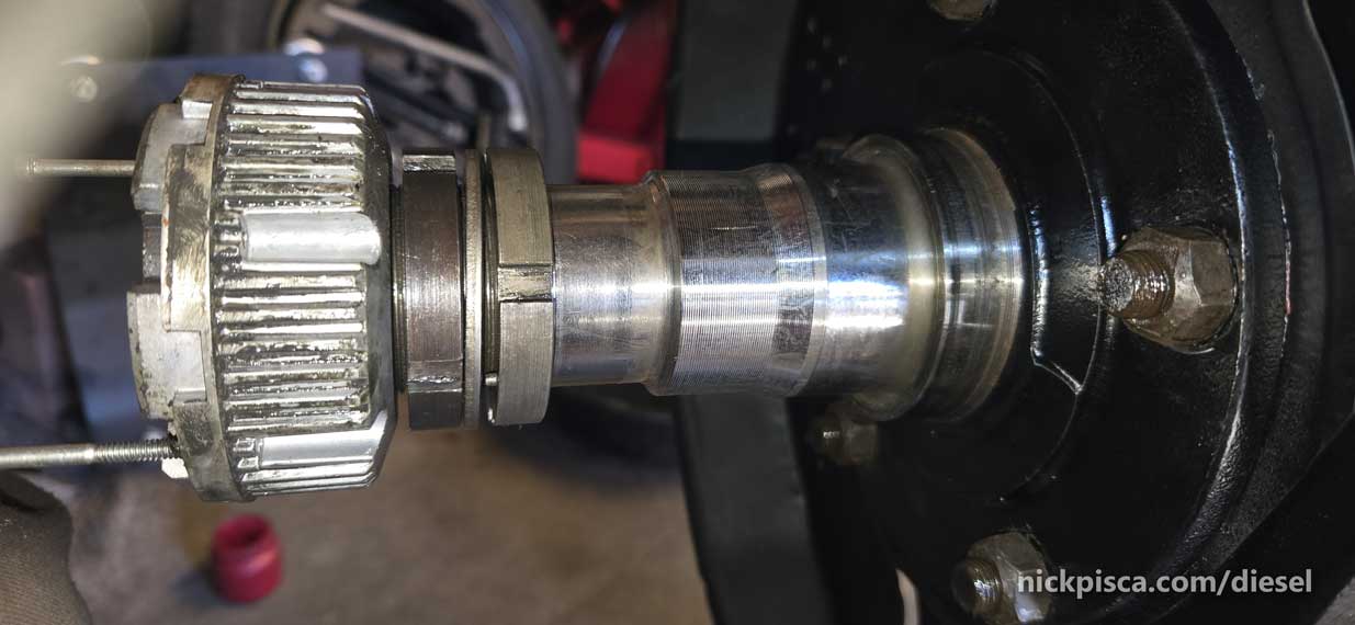
The spindle nuts are photographed here. These are not part of the lockout hubs, but play a role in securing the rotor and bearings at the proper torque.
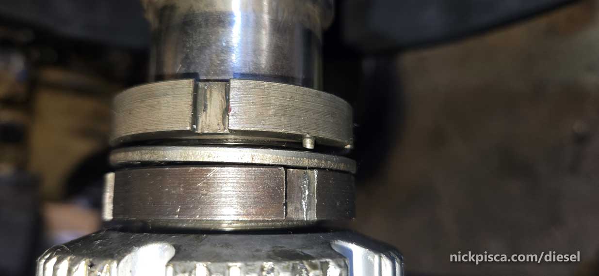
From back (away from the lockout hub) to front (closest to the lockout hub), the spindle nuts are a unique looking set up. The spindle nut WITH A NIB (see the photo above) must go back. Then the locking washer goes in the middle. Assuming you are securing the rotor, you’ll need to torque the back spindle nut to 50 ft-lbs, and turn it back a 1/4 turn. Then slide on the washer with aligning the nib.
Then torque down the front spindle nut to 150 ft-lbs. Once that is completed, there should be enough room to slide the Warn Lockout Hub. If you don’t torque it correctly, the lockout hub won’t have enough room to install the inner retaining clip.
Be sure to use some high quality grease to ensure all your bearings, races, spindles, and lockouts stay in good shape. I always use Mobil 1 Synthetic Red. Never been a problem with that grease.
Installation is the reverse of uninstallation.