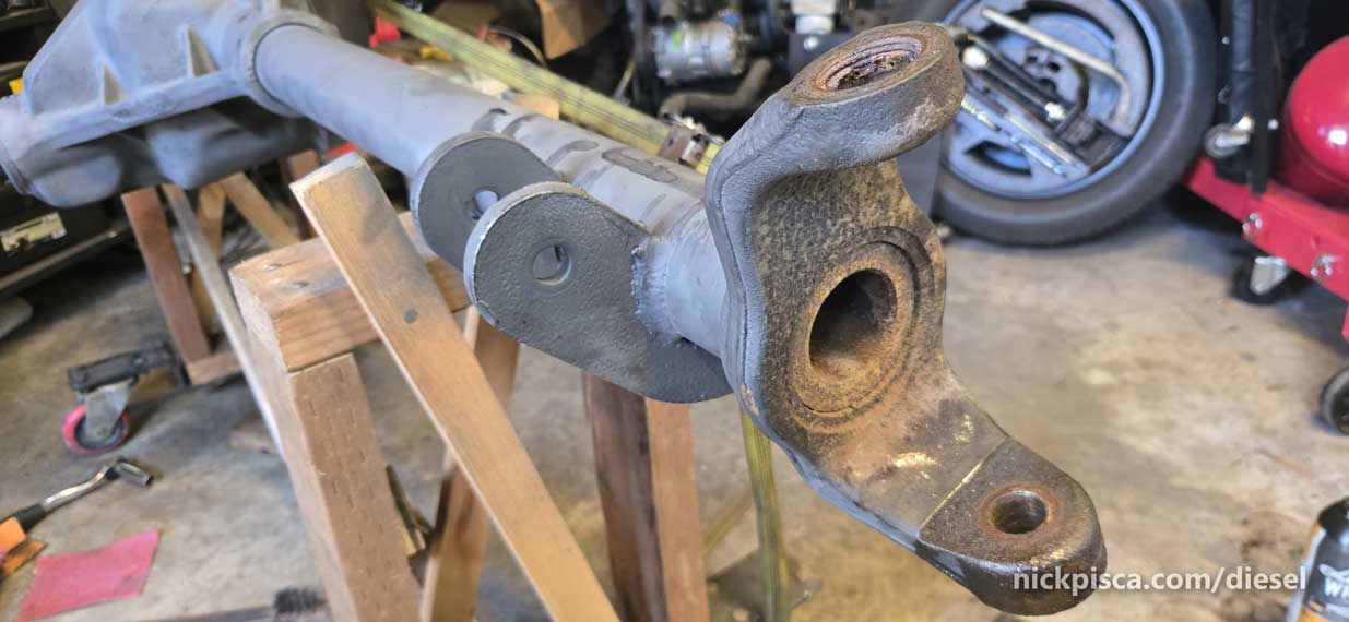
Once I got the axle hoisted up on the custom wooden jig with casters and diagonal bracing, I wheeled the beast into the shop for inspection and teardown.
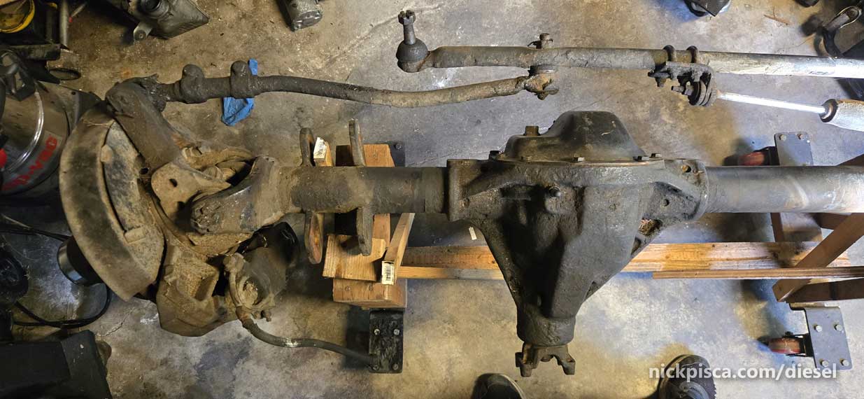
It’s going to take about 40 cans of brake cleaner and seven scrapers just to get to bare metal on the housing.
After checking all the numbers on the assembly, I found a clue. 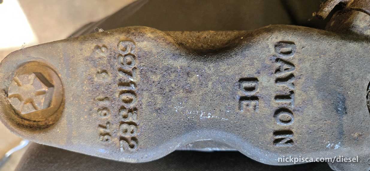
February 9, 1979. The calipers appear to be from the F250 or F350 disc brake assembly. Likely the F250 4×4, since the F350’s usually had a Dana 60.
If I search for parts in eBay or RockAuto, using this framework gets me really close to spot on: “1979 FORD F-250 6.6L 400cid V8”
That’s great, because now I can start the hunt for parts.
Here’s what I bought:

This kit was perfect. Worked really well for my Dana 44.
- Axle Shaft Seal: NATIONAL 5131 Info. Front; 4WD; w/ 8.5 IN Ring Gear; w/ Spicer 44-9F Axle (Returned. Didn’t use)
- Axle Shaft Seal. WJB / INMOTION PARTS WS5131 Info. Front; 4WD; w/ 8.5 IN Ring Gear; w/ Spicer 44-9F Axle
- Axle Shaft Seal. NATIONAL 2300 . (I bought this because a certain Youtube video said this seal worked for my Dana 44. It did not.)
- Drivetrain : Differential Pinion Seal. WJB / INMOTION PARTS WS5778 Nitrile Info. Front Outer; 4WD; w/ 8.5 IN Ring Gear; w/ Spicer 44-9F Axle
- GABRIEL 6802SE (Daily Driver) Info. RWD; Single System Steering Stabilizer;
- Steering : Tie Rod End. SKP SES2064L (Economy) Info. Fits Front Left Outer; 4WD; (This is a gamble. I cannot find Tie Rods that match the part numbers for the Tie Rod in the Quadravan Kit. I’m gambling this will be replaceable.)
- Differential Rebuild Kit. MOTIVE GEAR RA28LRMK (Master Kit) Info. Front; Dana 44 Axle;
- Ball Joint: MOOG K8195T (Daily Driver) Info. Front Lower; 4WD
- Ball Joint: MOOG K8194T (Daily Driver) Info. Front Upper; 4WD;
- Axle Shaft Seal. CENTRIC 41768001 Info. Fits Rear Inner or Front Inner; 4WD; Dana 44-6CF & 44-9F Front Axle. (This should be called a rotor seal. It fits in the inner part of the rotor, retaining the rotor bearing.)
- Axle Shaft Flange Gasket. FEL-PRO 55328 Info. Rear; 4 (In) Bolt Circle; 3.00 (In) Inside Diameter X 4-5/8 (In) Outside Diameter; w/ 8 Bolt Holes
- Knuckle Bearing. WJB / INMOTION PARTS WT23100 Info. Front Lower; 4WD; w/ 9.75 IN Ring Gear; w/ Spicer 60-3F Axle. (I’m a dummy. Didn’t realize I bought the wrong bearing for my rotors until the window to return was too late. That wasted $20 each.)
- Caliper Repair Kit. RAYBESTOS WK702 (Seal Kit) Element 3; Installation Hardware Included: No Info
Front; Dual Piston Caliper - Brake Hose.
DORMAN H36805 (Economy) Info. Front Left; 4WD; Standard Cab Pickup; To Serial No. Y40001(DO NOT USE. THESE DIDN’T WORK. SEE PICTURES HERE. USE BH80976 INSTEAD) - Brake Hose.
DORMAN H36810 (Economy) Info. Front Right; 4WD; Standard Cab Pickup; To Serial No. Y40001(DO NOT USE. THESE DIDN’T WORK. SEE PICTURES HERE. USE BH80977 INSTEAD) - Sway Bar Bushing. MEVOTECH GK8434 (Economy) Original Grade; Bushing Kit; Contains Bushings For Threaded End Info. Front; 4WD; w/ Components For One End of Link. (This is another gamble. There are many worn out bushings all over this Quadravan setup. These were on clearance, and I figured if I needed something, I could make these work.)
- Spindle Bearings. BCA NBSBK1 Kit Info. Front Inner; 4WD; w/ 8.5 IN Ring Gear; w/ Spicer 44-9F Axle. (I used the seals from this kit, but not the spindle bearing. I liked the old bearings better. These had some plastic in the middle that looked flimsy. The old spindle bearings looks stirdier.)
- Ball Joint. MOOG K8194T (I ended up missing on ball joint upper from the first order… not sure what happened. This didn’t match the other side, but it appeared to be ok).
Next was determining my axle ratio. There is an easy way to do this. Take the pumpkin cover off and look at the numbers on the ring. Oooooor, you can just turn the pinion gear at the yoke and count the rotations.
I ended up with almost 4 turns for 1, with a little extra. My bets are that gearing is a 4.10, which is not the same as my 3.55 gearing in the rear. If I like to drive in 4WD without constant clunking and tire squealing, I’m going to need to source a good 3.55 pinion and ring gear.

I didn’t read a lot of good things about this ring and pinion, in terms of getting patterns to work propertly.
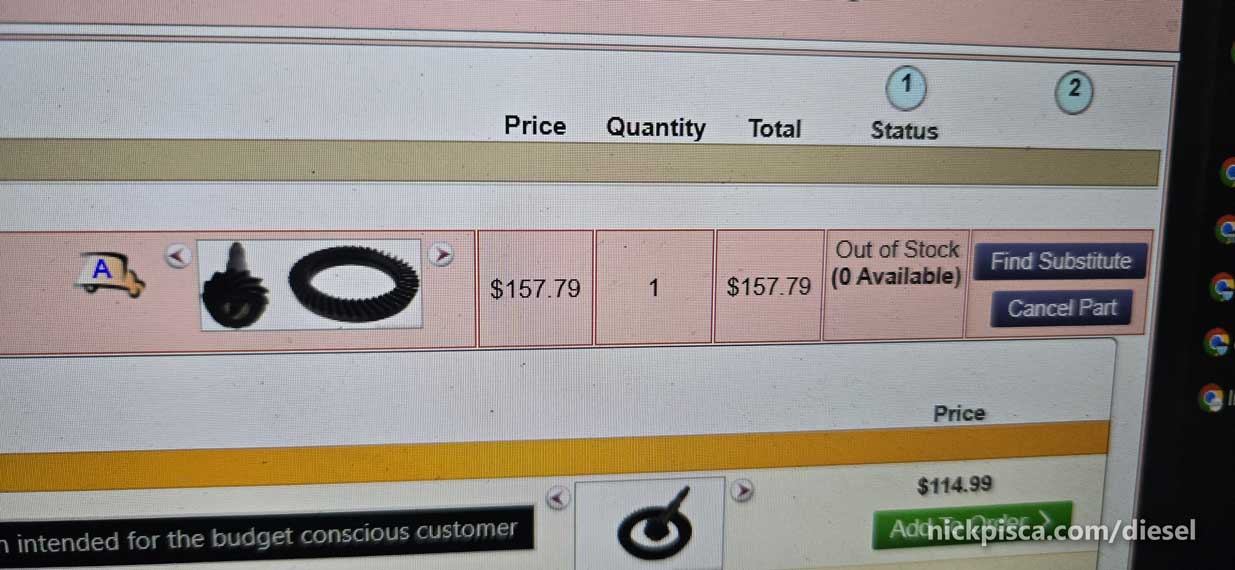
A quick google search showed many options, like Summit trying to sell me a new gear set for almost a thousand dollars. Nah thanks. I did find a new set of gears on Rock Auto for $157. Not really too thrilled about the bargain basement pinion parts either. Apparently there is not a middle ground, so I added the part to the massive order from RockAuto.
DANA 10001714 (Economy) SVL Info
Front; w/ 3.54 Gear Ratio; w/ Dana 44 IFS Axle
One day later, while disassembling the Axle, I get a literal call from Madison Wisconsin. It was RockAuto sending me a “friendly” message that my part doesn’t exist. Well Thanks.
I hop back on to the computer to find this message.
There must be a way to find good parts without losing an arm or a leg? I started calling around locally. I found a “junkyard” on car-part.com that apparently is in downtown LA, which is odd since I’ve lived here for 23 years and don’t recall any such yard. The closest place is in Wilmington.
I decided to call them just to find out what is going on. Ended up talking to Marty from Southern California Truck, Van & 4×4 Parts. http://www.southerncaltruckparts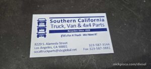 .com/
.com/
I’m going to post their website another time. http://www.southerncaltruckparts.com/
And another time: http://www.southerncaltruckparts.com/
Why am I blasting you with Southern California Truck, Van & 4×4 Parts? Because they have everything. They are not just a junkyard. They are a massive inventory of parts for everything you could ever imaging. And they’ve been around for almost a hundred years.
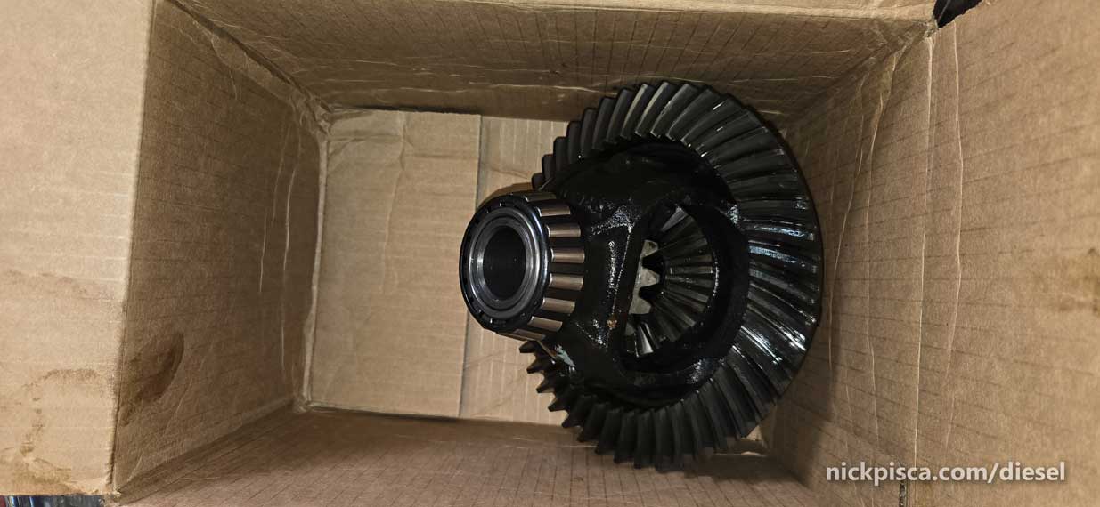
Marty proceeds to ask what I need. I said I’m looking for a front (reverse gear) pinion ring and gear for the 1979 F250 or 1988 Quadravan conversion for the Dana 44. He didn’t even ask much else, he just said, “I’m sure we have it laying around.” At first, I wasn’t impressed. I didn’t want to trek all the way around LA in my car to drive there and not have the part in hand. I was wrong. Marty has everything.
I arrive to the pinion gear and ring just sitting there on the desk.

Not only are these EOM parts, but the price was outstanding. $250. This is even better than new Chinesium for 3x the price. The parts had some dust on them, but I was planning on cleaning them up and putting new bearings on shims on anyway, so they are good to go.
Marty gave me a tour of the back lot. Every transmission, T-case, driveshaft, axle assembly, you can think of. He gave me a bunch of advice on how to disassemble the parts, and get everything ready for the pinion swap. He even gave me a cheat sheet for setting and testing the patterns for the differential.

ENOUGH SHOPPING.
Get some work done.
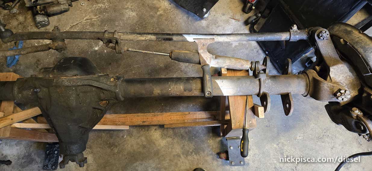
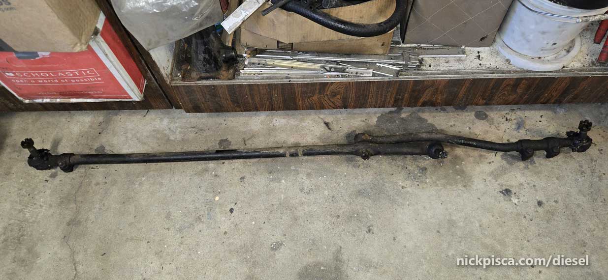
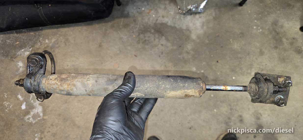
Rip those Tie Rods and steering linkage off.
This steering stabilizer looked like a sasquatch humped it.
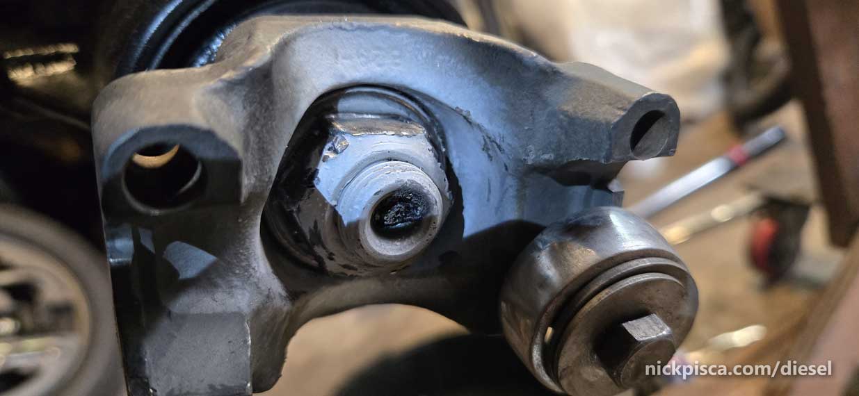
Let’s get those brake calipers off.
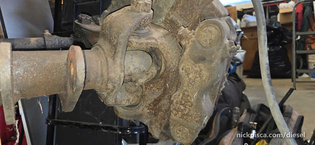

UUUUUUUUGLY. Ford used the handy-dandy slider retainer. It was so rusted, along with it’s rusted retaining bolt, that I had to use a tap and die set to get it back to new.

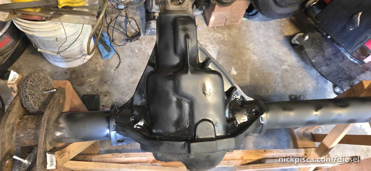
I’d like to walk around my shop without wiping 40 years of dirt and diesel all over my clothes. Let’s clean up the housing a bit so that the vast majority of gunk doesn’t get all over me, and more importantly, not in the differential.

I wish I had a sand blaster. Oh well. Hit it with some primer to keep the rust at bay.
Time to return to the Tie Rods. They are totally trashed. Won’t move or turn wthout being chunky and messed up.
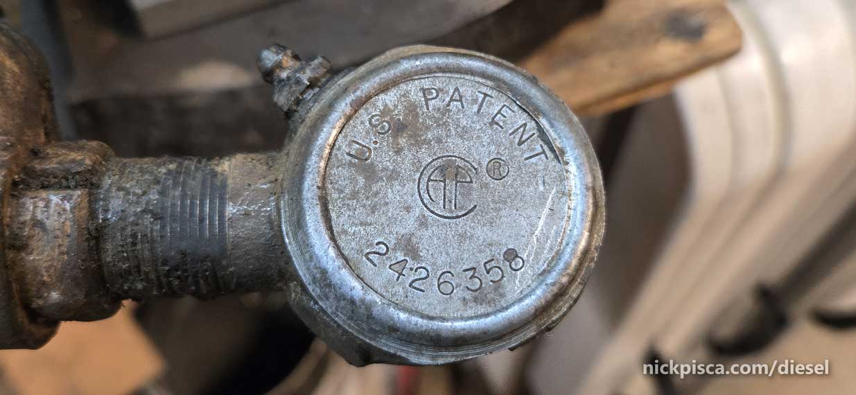
Got enough feces off the tie rod end to actually see some numbers:
I’m sure these are great, but I’m hoping for an alternative.
Tie Rod End Part number: 2426358.
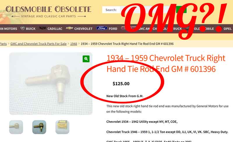
Sure. Should be easy enough to find. Uh no.
One website was asking $125 per end. They are literally listed at parts from the 1934-1959 Chevy truck from the Oldsmobile Obsolete website! I’m a little surprised that a truck kit from 1979 would use that kind of old tech, but here we are.
Maybe I can reuse my old ends… but they are messed up beyond repair.
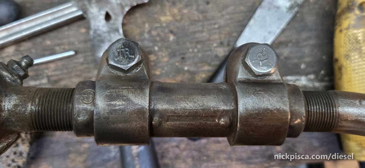
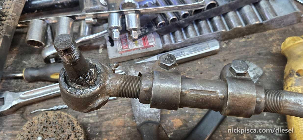
Tie Rod Coupler. Looking to use this but find a more contemporary replacement Tie Rod End instead of one from the Depression Era.
These aren’t complicated items. They sandwich into a retainer that ends from the Tie Rod itself. How complicated can it be.
Decided to invest in a little experiment. Try to buy a replacement and use the same coupler retainer to try an alternative Tie Rod in the future.
The center link looks better than the ends. They cleaned up well and look like they are reusable. If possible, I’m going to look for replacement rubber caps to keep my grease all in one place.
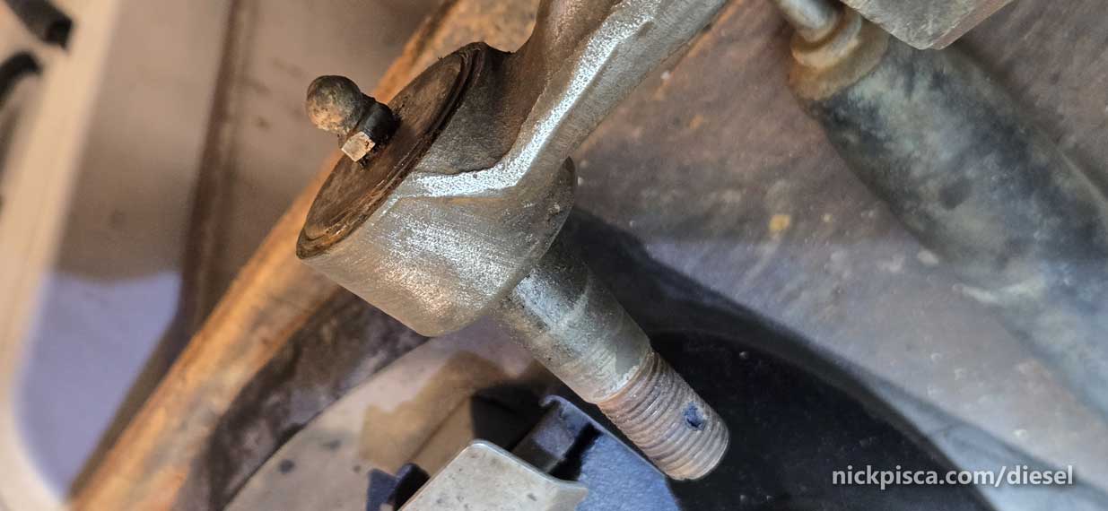
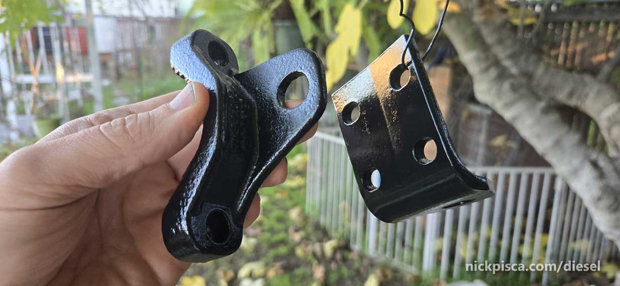
Jeez, these rotor protectors are rusted, bent out of shape, and on their last leg.

Sigh…. As you can tell, I’m apprehensive to rip this apart. I’m getting lazy in my old age.
Let’s stare at the Warn Lockout Hub for a half hour and eat a sandwich.
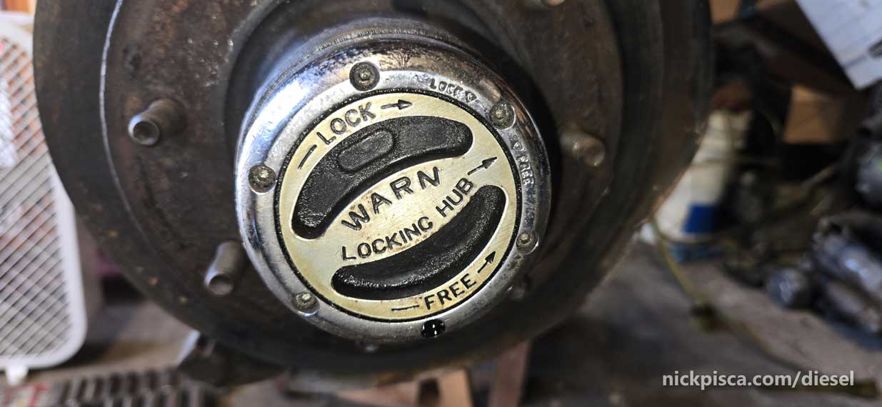
After staring for 45 minutes, I finally got the urge to get back to work. Need Glenn here to kick me in the ass.
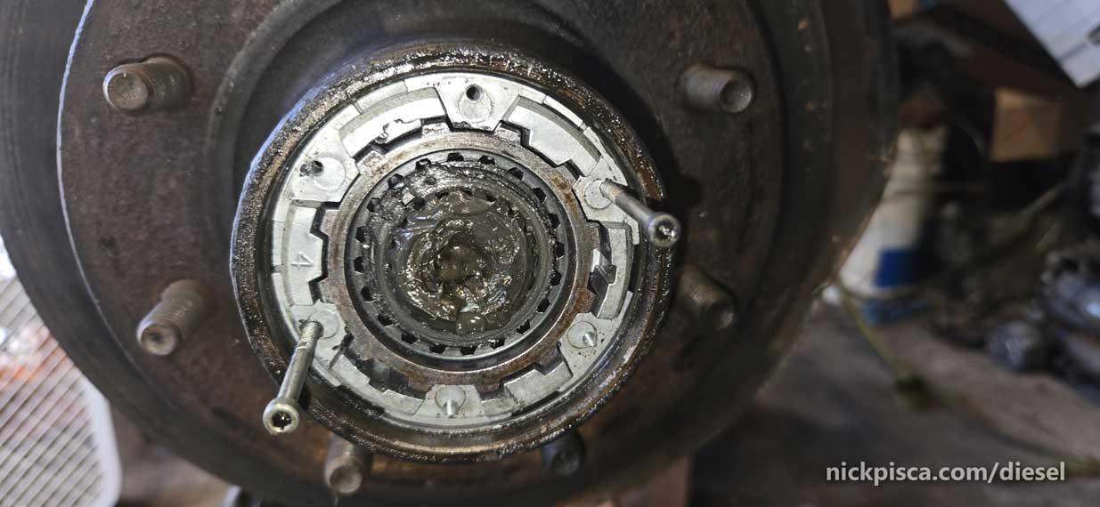
Thankfully the Allen wrench unscrewed the machine bolts without any rust or issues. Phew.
Remove the two retaining clips.
Inner:
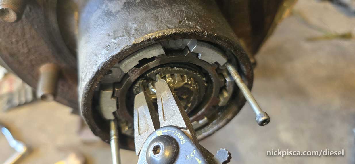
Outer. (NOTE: Be careful with a dental pick on any of these surfaces inside the axle.)

Slide out the Lockup Hub mechanism, and it looks like something out of “2001 – A Space Odyssey.” I’m getting hypnotized.
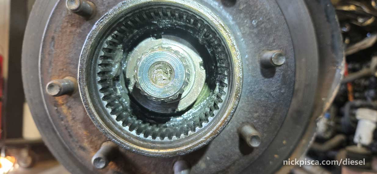
While I’m lazy, it doesn’t stand in the way of me being cheap AF. I see a fancy spindle nut in there with four niches. I don’t have the fancy tool to remove that. That won’t stop me from finding stuff in the shop to get that nut out. So I made a fancy PVC DIY spindle nut remover. It slid over the spindle really nice, and for a moment, I thought it would work. WRONG.

As much as I don’t want to shop Amazon, this was my only option.
Busted the plastic nibs right off like it was butter. These spindle nuts are torqued down over 100 ft-lbs, so I knew it would have been a long shot.
Since it was near the end of the day since I was dinking around too long, I called it a day and ordered Dana 44 Spindle nut socket.
“OEMTOOLS 25072 Dana 44 4WD Lug Nut Spindle Socket – for Dana 44 Axles Only – GM, Dodge & Select Ford Applications”
$14.99 on Amazon.
That’ll take a day to arrive, time to keep sanding, grinding, and scraping all the crap off the axle.
Cleaned up the Steering Stabilizer parts. Part NUMBER: 88148 or 86148
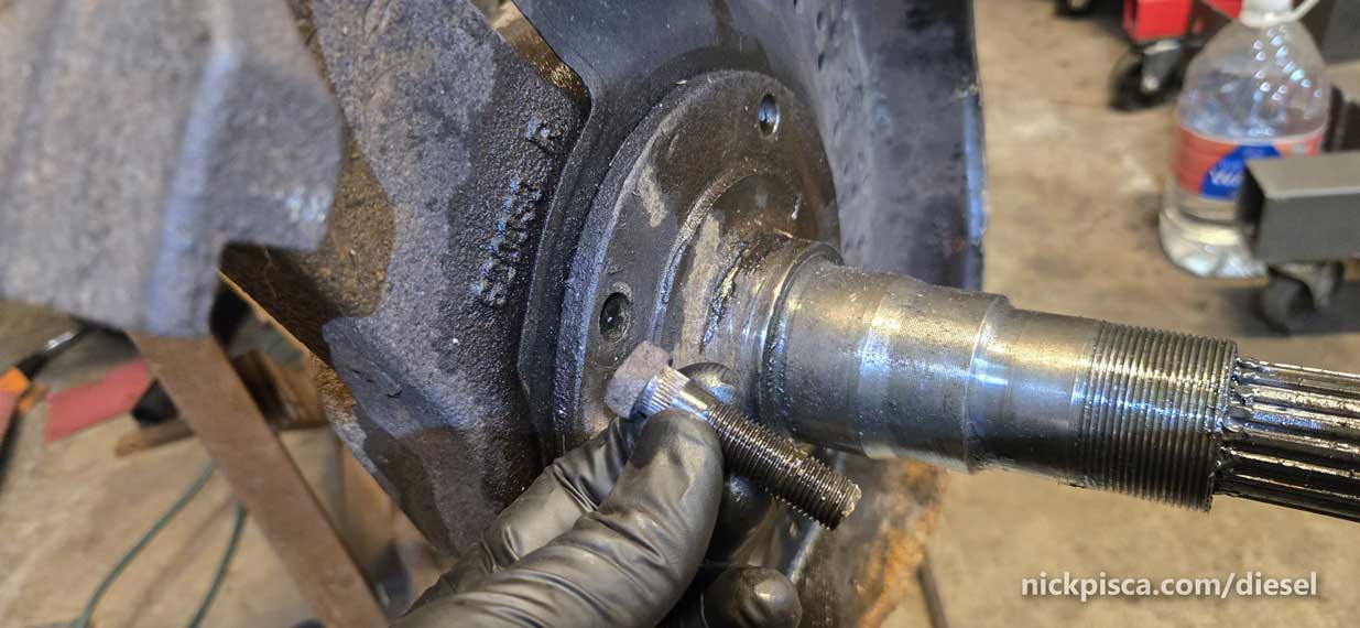
Next day the socket arrives, wooo. Time to get back to work. Remove the spindle nut, and there is still more holding that rotor on.
There is a fancy spindle washer with holes. This is important. It mates with another nut on the inside.
Removed the inner nut and voila, the rotor just slides off the spindle.
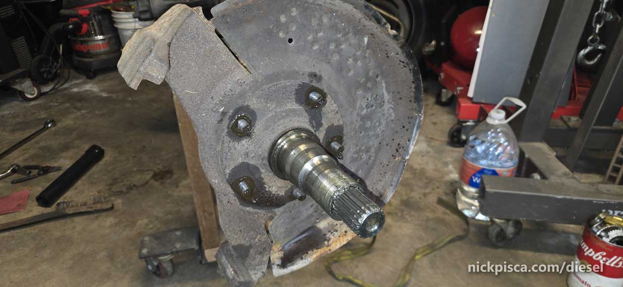
The next part is the hardest part. Apparently, the engineers designed the spindle to come off the knuckle, but good luck. I spent a lot of time trying to pry it off of the caliper harness, but nothing was budging. The spindle had fused to the knuckle, and no amount of work would get it off.
I posted this to the IDI Facebook group, asking for help.
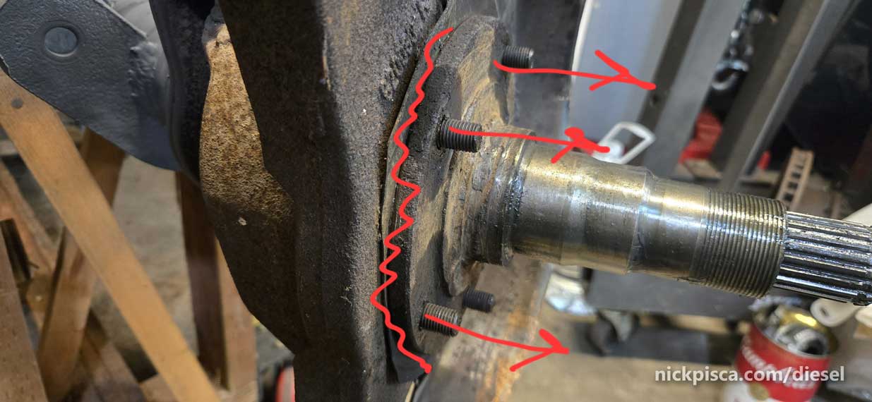
One guy suggested that I tap out the bolts, which slid out easy.
Even with the bolts gone, the spindle still wouldn’t move. I doused the mating surfaces with penatrating oil.
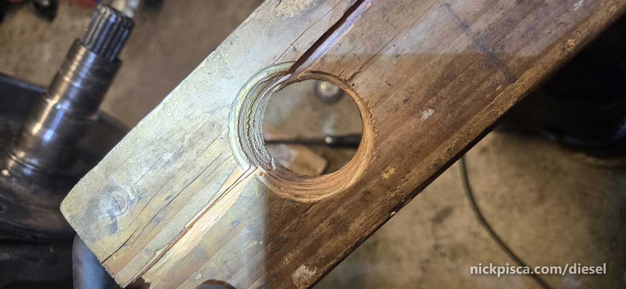
Next a guy suggested using a 2×4 with a hole to pry the spindle off. That broke the wood.
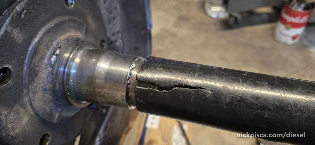
Another guy recommended putting a huge pipe on the spindle and wiggle it off the knuckle. I broke the pipe.
I was losing faith, until I ground down the tip off a masonry chisel, and tried to hit at it with a BMF Hammer from the inside of the knuckle. SUCCESS! Watch here:
Now you kids know how to get out of school.
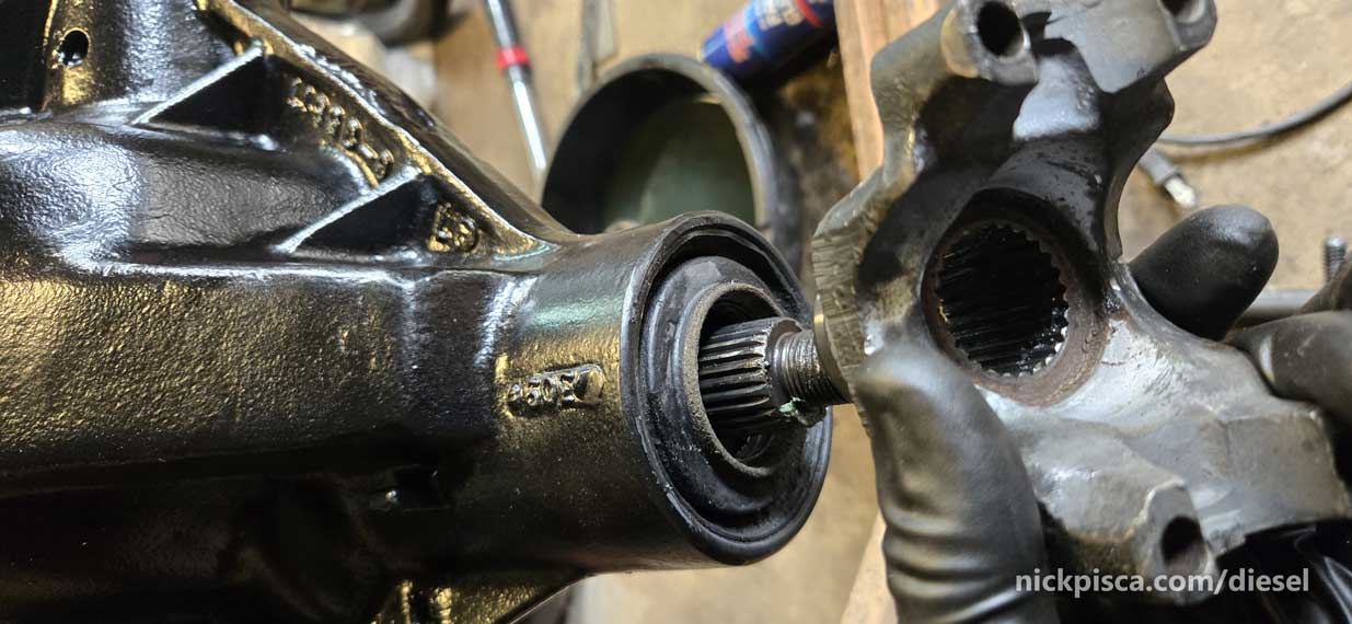
Things went a lot faster now. Spindle popped off. Knuckle came off easy with a impact driver. Axle shaft slid out without any effort, aside from gathering rust on the way out.
The ball joints are trash, and they popped out with a hammer.
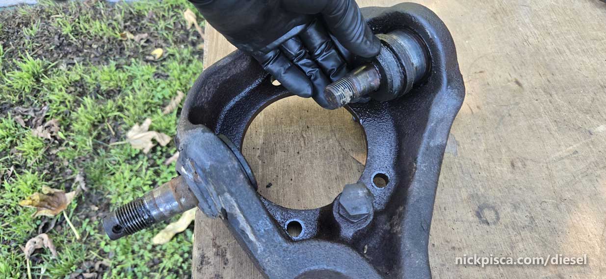
Those old ball joints look like they need E.D. supplements.

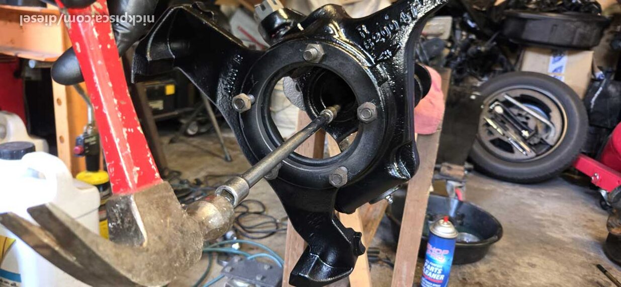
Caliper holder and the rotor protector need lots of TLC.

I looked up to see if I could find replacement rotor protectors. Part No: 620189R and 620189L
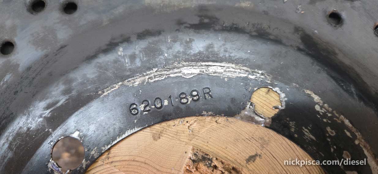
You can see all the damage the thing took by all my prying and chipping trying to get that spindle off. I’d like to replace these, but I couldn’t find the part online. I’ll have to repair these with sheet metal tools.
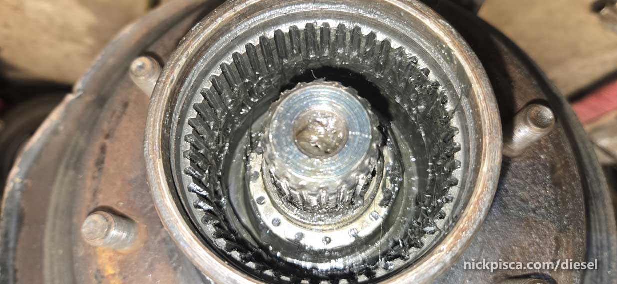
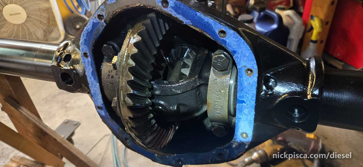
Lastly, it’s time to open that pumpkin. Let’s see what we got.
I marked my bearing caps so that I know which is Right and Left, and their orientation.
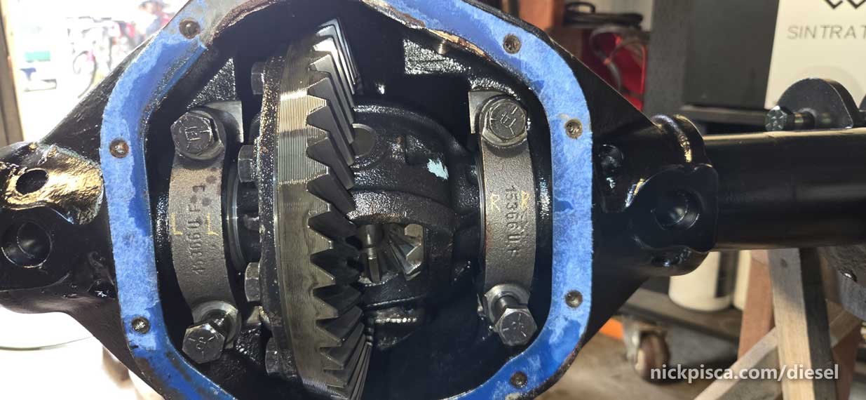
It’s important, because if you mix those up, they won’t seat well for the bearing races.
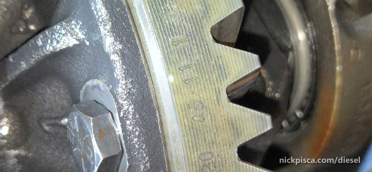
AHHHH HA!!! 45 11 1
45 divided by 11 = 4.09090909 which is rounded to 4.10 axle ratio. I was right!
Let’s slide that differential carrier out.
It’s not easy, because the bearings are shimmed to be within a few thousandths of an inch in the housing. A youtuber had a great suggestion. Slide a 12-inch-x-1-inch piece of 1/8″ thick aluminum in between the spider gears. Then turn the yoke. It’ll use leverage to push the carrier out. Just be ready so that it doesn’t just pop out on the floor!
She’s hollow.

Don’t throw away the races. You’ll need them in the future, but for something else.
Let’s get a gander at the inner seals.
I don’t care if they are in good condition. I’m replacing them while this is all apart.
Getting the yoke off was a PITA.
I used heat 3 times, and lots of penetrating oil. Nothing was working. I knew I cooked the out pinion seal doing all of this, because the nut was red hot. That made the yoke hot, and the pinion shaft hot as well. Those plastic seals can’t hold up to that kind of heat. I was committed now.
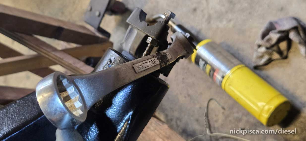
I used a massive pry bar and my biggest closed end wrench on a pipe in the yoke slots, and that wouldn’t make the pinion nut budge. Whatever thread-locker they used must’ve been military grade.
I couldn’t get my grinder in there (not enough room), and my dremel didn’t do enough damage. I landed on using my power drill with a 1/4″ bit to drill the opposite sides of the nut. Then use the dremel to carve away the small wall between the end of the nut. Once I hit threads, I moved to an inner area.

It’s ugly, but it loosened up the nut enough to chip it off.
The yoke doesn’t just slide off. You need somekind of steering or balancer puller to get it off the pinion splines. I don’t have a picture of that, but you get the jist.
The pinion slides out. The oil slinger plate gets in the way of the internal flanges of the axle, but the rest is fine.
Here’s a video of my pinion that I made later on, but it shows how to install the bearing the easy way.
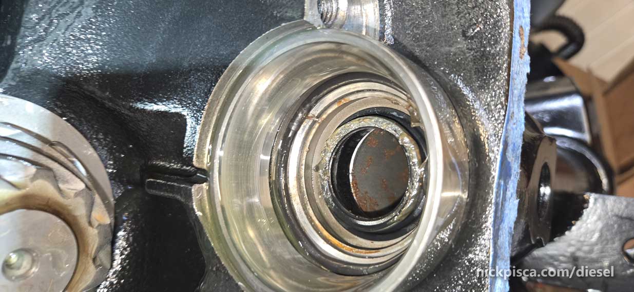
Using a screwdriver, pop that burned-up pinion outer seal out.

Almost DONE with the tear-down!!!
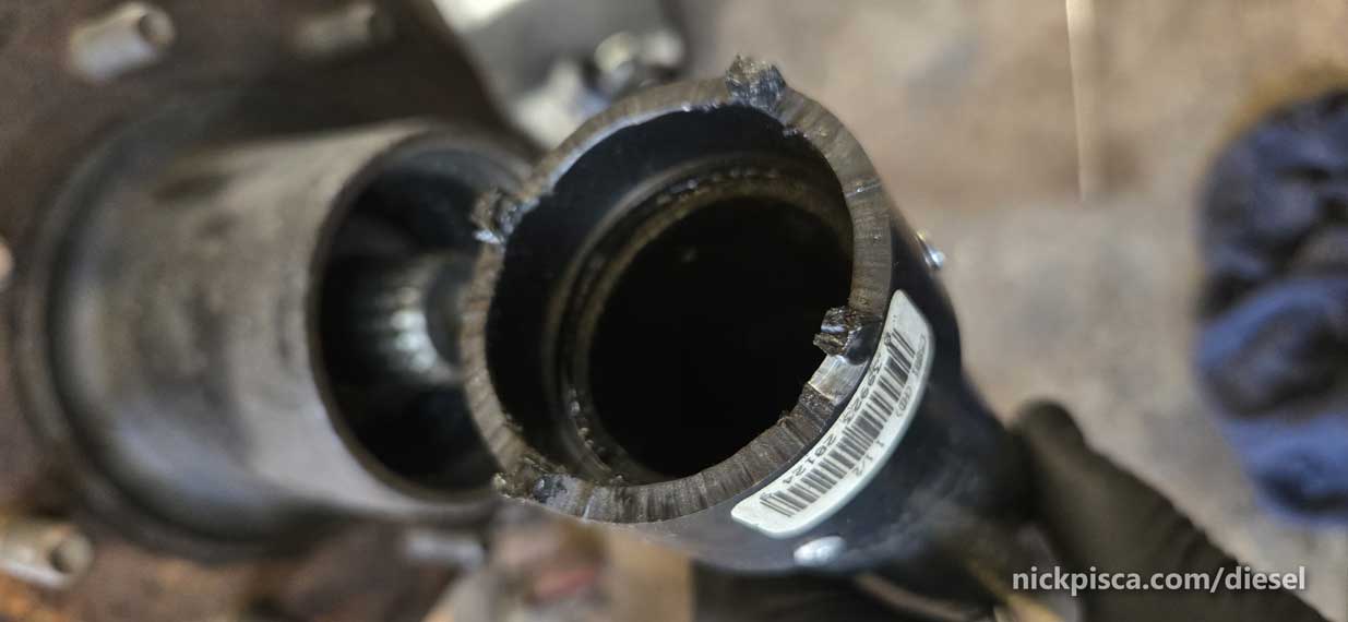
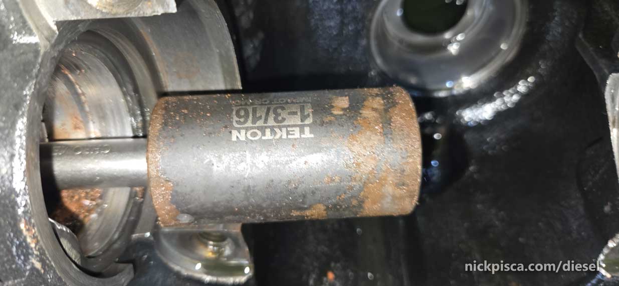
Last item is to pop out the side mounted axle shaft seals on each side of the carrier bearings.
Using a 1-3/8″ socket on all my 1/2″ extensions through the axle shaft, I tapped the seals out toward the center of the diff housing. Here’s the socket on the other side of the seal, looking from within the diff housing. You can see the hexagon where the socket is.
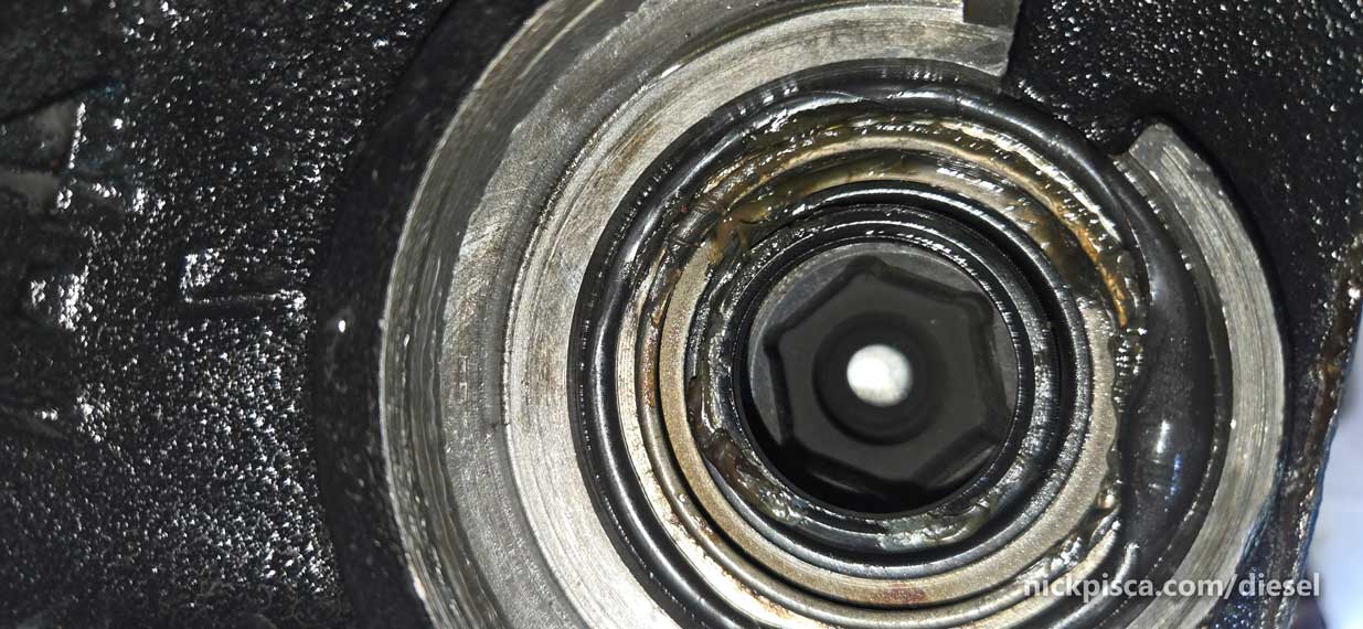
Using a hammer, I tapped on the extensions:
After a few taps, the seals popped into the diff housing.
Lots of rust inside that housing. Terrible design that the outer axle shaft doesn’t have a seal.
AXLE TEAR DOWN COMPLETE. Time for fun stuff.