1998 VW Jetta
TDI VO Conversion Installation Thread Return to Main Page
Dual
Tank System < 1 2 3 4 5 >
WVO & SVO Compatible
Design and
Installation: Nick Pisca, July 2007
Rear Components and Bundle Installation:
The
following images show how the components and bundle were installed.
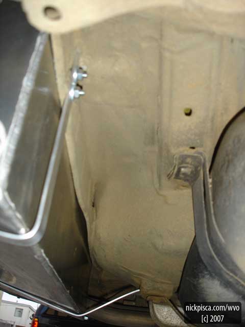
EMPTY SPACE UNDER THE
CAR:
When I
first planned out the rear system, I speculated that the components (a heat
exchanger, fuel pump, and filter head) would all fit besides the tank directly
behind the rear tire. Once the tank was
completely installed, it was apparent that this would be impossible. The HotFox fittings
would obstruct all side-layout scenarios, so I moved to the space between both
tanks under the car. This space was
eight inches deep at its highest point, which forced the filter head to be
horizontally or angle mounted. The filter
head was 9 inches tall.
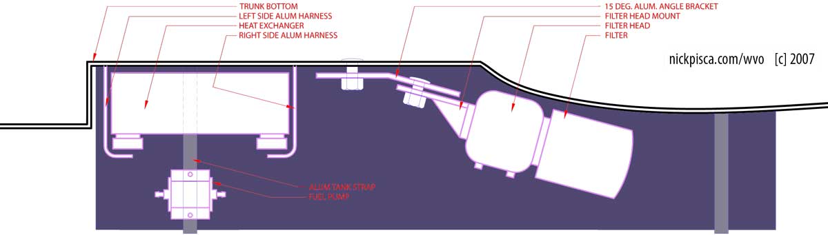
The
filter head required a custom metal angle to set it at fifteen degrees. I wanted it to be as steep as possible to
reduce spilling oil when a filter required changing, but fifteen was the most I
could get.
Next, I
placed the 20-plate heat exchanger up against the tank and underside of the
trunk floor. To secure it, I fabricated
two bent aluminum strips on each side.
If I needed to pull it out for some reason, I could just push back this
harness. They hook and connect to the
top of the exchanger, which is upside-down.
I
thought the fuel pump could still be mounted on the side, but that proved
difficult again because of potential hose kinking. A spot directly the heat exchanger worked
best. Glenn predicts my cheapie fuel
pump will give out soon anyway, so mounting where it’s easy to remove would be
good. I didn’t even bolt it in place;
the mounting was accomplished by using some aluminum wire loops.
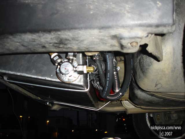
HOSE ROUTING:
Since
most of my fittings are all pointed downwards, I needed to be creative to avoid
kinks. AutoZone sells Goodyear brand
heater hose coils that are meant to hold a specific bend in a specific
location. They slide onto the hose and
have a metal backing that retains the desired shape. This is important for my design, for I can’t
have any hoses dip below the tank; if it did, not only would I lose all my
heat, but also it could get caught on something when I drive.
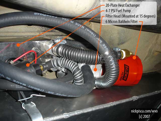
I found
that these coils have a secondary effect that reduces kinking for moderate
turns. Since the store-bought coils
still have a little play with the hose, it can still kink or stretch, so I used
some of my aluminum wire to produce my own.
It doesn’t have the backing, but it still works really well if it’s
snug.
I would
have used more 90 degree bend fittings, but in most cases, it wasn’t
possible. The heat exchanger had some
crazy custom hose fittings that I could replace.
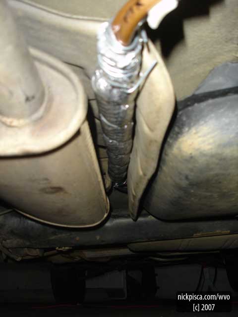
EXHAUST SYSTEM BYPASS MINI-BUNDLE:
For most
of the bundle, I used large extruded insulation with Hose-On-Hose (HOH)
heating. This insulation had a wall
thickness of 3/4” and averaged a diameter of 3.” There was a small distance from the back of the
car to the suspension system that couldn’t accommodate this large bundle. So before I installed the large insulated HOH
setup, I made a thin segment out of 3/8” copper and aluminum bendable pipes. Just in case you don’t already know, you
shouldn’t use copper hoses or fittings for the VO system. There has been a lot of research on this
topic and copper can react with vegetable oil.
This
smaller bundle is probably a better conductor of heat transfer anyway, because
I connected the two copper and single aluminum tube
with silver solder.
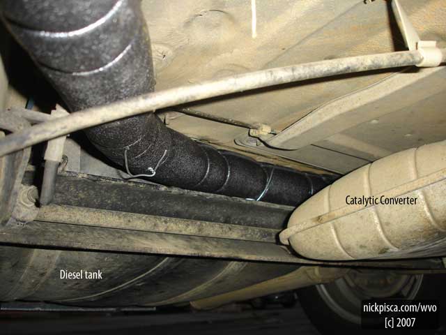
START OF THE BUNDLED TUBES
Since my
major HOH bundle starts by the muffler, I was able to make some steep bends in
the copper and aluminum tubes from the mini-bundle. This lifted the tubes up against the floor
boards to clear the suspension system.
As you can see, I wanted to have a lot of insulation to protect the
bundle. These were 6-foot segments from
B & B Hardware and I used zip-ties to make an A-A-B pattern.
The
make-up of the bundle comprises three 3/8” fuel hoses (coolant-in, coolant-out,
& fuel-supply) and a 5/32” vacuum tube for a VO return.
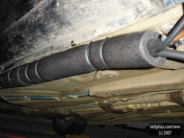
POTENTIAL REWORK
The only
part of the system that makes me cringe is the mid-section of the bundle. There wasn’t a lot of room for a three-inch
diameter tube to go for this 3-foot distance.
If you look at Jeff’s configuration, he ran HIH and that afforded him a
low-profile system. On mine, it does
hang down pretty far. I’m tempted to
remove this section and make another mini-bundle to run closer to the floor boards.
If I had
to start from scratch, I’d contemplate doing the whole bundle with aluminum
3/8” bendable pipe. It’s only 89 cents a
foot and if you can solder certain places together, you’ll essentially have a
twenty-foot long heat exchanger. Glenn said
it would be a pain in the ass to route the lines, but since it’s not being
tracked inside the car, I don’t think it’s that difficult.
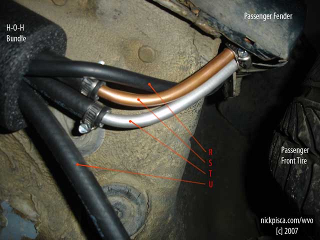
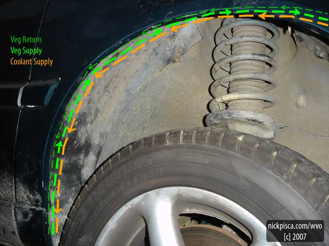
COOLANT RETURN SPLITS AWAY:
I split
the coolant return away from the bundle right behind the passenger-side
tire. This saves some space when I set
up the front heat exchanger. From the
Image above:
R: VO Return
S: Coolant Supply
T: VO Supply
U: Coolant Return
Once
again, I used a section of the copper and aluminum bendable hose to manage the
transition through the fender. If I just
bent the rubber hose into the fender, it could kink. I re-bundled the three remaining tubes after
the interstitial metal segment. Also,
this metal area is insulated with reflectix (not in
the picture.)
FENDER AREA:
This was
a good find for hiding the bundle. If
you remove the plastic inner fender, there is a whole bunch of room for not just
the bundle, but if wanted to install a third heat exchanger, this would be the
place. I’m even tempted to move my front
heat exchanger to this location, because the upper left side has a lot of extra
space. I don’t have an image of the
system with the inner fender removed, but this picture shows how the three
tubes work.
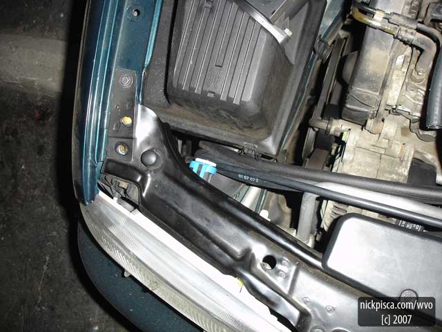
COOLANT RETURN:
The
coolant return hose emerges up the firewall and connects in the heater core
hosing in a series configuration with a simple brass 3/8”-to-5/8” reducer. The coolant supply hose (not pictured) runs
continuously around the engine and follows the VO lines from the selector
valves to the rear “mini-bundle.”
Later, I
came back through these areas and added some lower profile extruded pipe
insulation to this line. Due the
conversion, the heater core is now the last element in the series circuit. Saving as much heat as possible will decrease
my warm-up time.
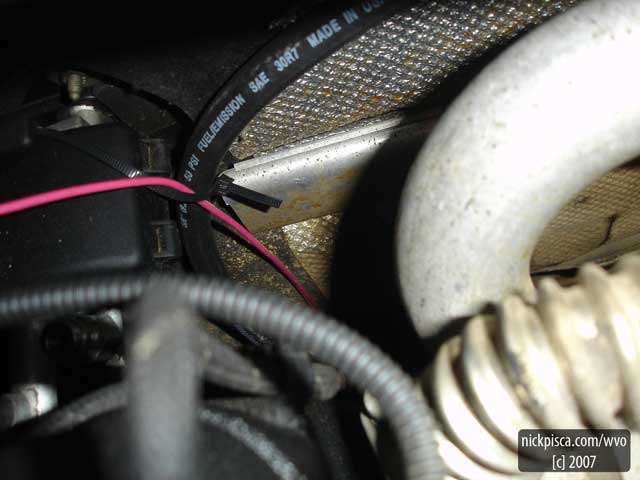
Also,
the image displays the 14-gauge pink wire that is the load for the fuel pump in
the rear. I ran it from the back to the
front, which may have been a mistake. Later
I found that the Jettas have a few extra slots for
diesel supply and return. Look in the
engine compartment near the diesel can filter; if you see a blue plastic line,
follow that to a metal tube that runs down through the floor boards. If you can fish your electrical down this
path, you can have a really clean system.
END OF THE BUNDLE:
The
bundle completes it run in front of the air filter housing. I found a reasonably-sized hole that
accommodates an uninsulated cluster of hoses. I ran a 5/8” hose from the heater core for the
first part of the coolant supply line because I have a theory that the thermal
mass will retain more heat. At the
bottom of the air filter housing, there is a heat exchanger that you’ll see
later in the thread. The heat exchanger
has a 3/4” coolant fitting so this works pretty seamlessly coming directly from
the heater core hosing (avoiding a reducer).
This was
all post-insulated once the engine portion of the conversion was completed.
[c] 2007 Nick Pisca . www.nickpisca.com/wvo . Waste Vegetable Oil Awareness and
Travel . www.nickpisca.com