
Over the last few weeks, I have been testing the limits of my Sintratec Kit. Some of my prints had to be aborted due to curling on the edges that either caught the applicator fin, or were so precarious, that I just killed it anyway. I would sleep easier at night knowing that my edges were solid everywhere my STL’s are located, rather than gamble on a print with the potential for catastrophic failure.
So that begs the question: How do I know what areas are safe?
Are there hot spots in the model that would produce powder fusion, and lead to my models having plaque or fused together? Are there areas where curling always occurs? What about areas that delaminate? Can we fine tune the temperatures of the bay to maximize the footprint of sintering success?
These were all questions on my mind when I thought of a plan to test the efficacy of my Sintratec Kit. I would need to develop a model that will cover a vast swath of the bed, while also inform the excavator where it came from. I figured a grid with identifiers would suffice.
First, I needed a parametric model, so I could precisely adjust my calibration grid if necessary. I like to use CATIA, but their 3D text utilities are atrocious. I’ve always wanted to remake their 3D text into something much more lightweight, so I used some Knowledgeware scripting to output some basic numerals from a string parameter. Then encapsulated it in a UDF.
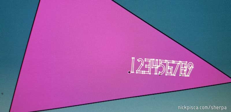
I’ve been meaning to to that for ages. Every time I used to 3D print my models and use text, I had to import my datum model to Rhino and I hate that. I’d much rather use a parametric model instead.
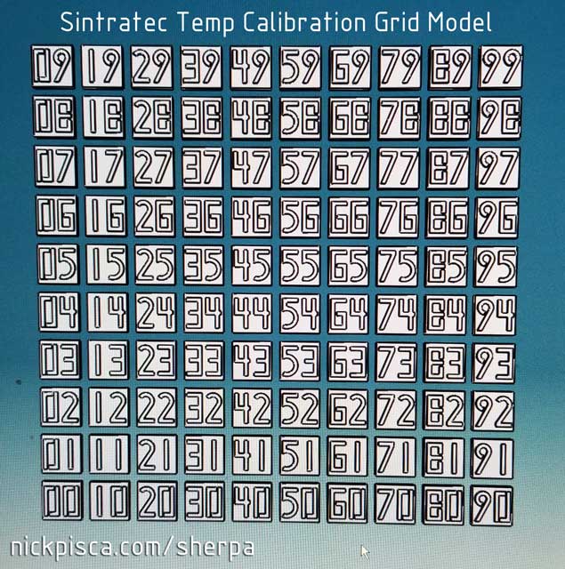
Then, using a tiny script I made, I produced a 11cm x 11cm grid of 9mm squares. Solidified the squares and applied my custom UDF’s to the surface, mirroring the underside as a pad and top as an extrusion. This way, I can test the laser sintering capabilities of the underside versus the top.
 Using another simple STL exporter script, I got a bunch of STL’s from CATIA and brought them into Maya. The only reason why I did this was, I still haven’t figured out the math to properly mis-orient the STL’s in Catia to bring them into Sintratec Central properly, like my Maya MEL exporter does. So bringing them from CATIA to Maya allows me to use my exporter and get them in Sintratec Central on the right spot with their “reset XYZ” button.
If you are interested in using this Sintratec Central Calibration Grid, here is the download for the STEC File (Click image to the right:)
Then I ran the job. It’s a short model, being only 4mm tall. If all goes well, you can see some great sintering across the entirety of the bed:
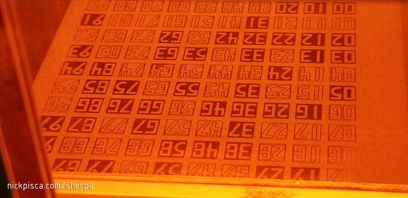
However, it is EXCEEDINGLY likely that your entire bed will perfectly sinter the full 11cm square. Don’t get me wrong; That’s not a bad thing. In fact, Sintratec recommends that you stay within a 9cm x 9cm footprint to ensure your model doesn’t curl or fuse and destroy your machine.
However, I’m in the business of pushing this kit to the limits, so I’m going to see what it can do. This Temperature Calibration Grid allows me to fine tune the sintering functionality in every square millimeter of this bed. The process here is finding a Goldilocks Zone of temperature: Too hot, and your powder will fuse together like a brick; Too cold, and the sintering will curl. Even being a little too warm will fuse the powder on the surfaces of the STL’s in the center (squares 44, 45, 54, and 55), and it will cause a “plaque” that is really hard to scrape off. Even being too cool can be bad, because even if just one small STL has a tiny curl, that one curl can destroy an entire build.
Some of the things you’ll encounter are curling, fusing, plowing, shadows, plaque, and delamination. Here are some examples:
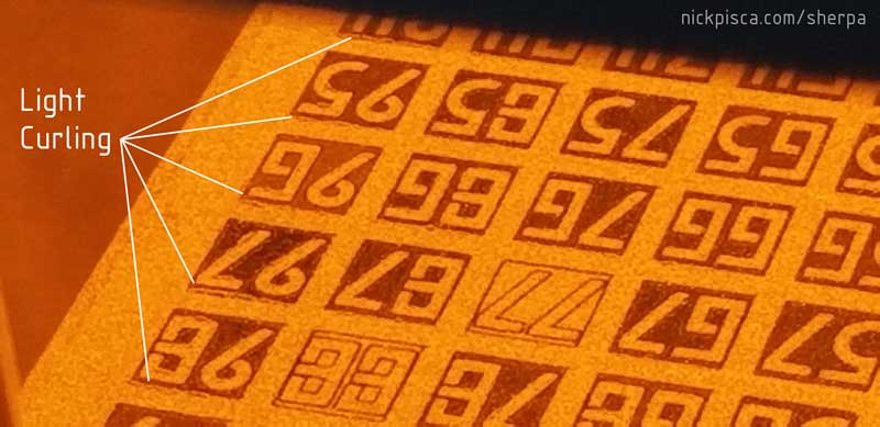
Depending on the surface temperature, light curling can occur. This isn’t the worst thing, but it can lead to delamination of the plastic, and the potential for catching on the application fin. This image probably captures what I’d consider to be the maximum allowable curling on a build before it would be a risk.
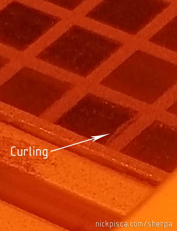
This image capture severe curling. It is highly unlikely that this layer will survive when the applicator fin applies a top layer. It will likely catch that curl and destroy your build. Increase temperatures to reduce curling, however, do not increase them greater than 174.0 deg C because the model will fuse together like a brick.
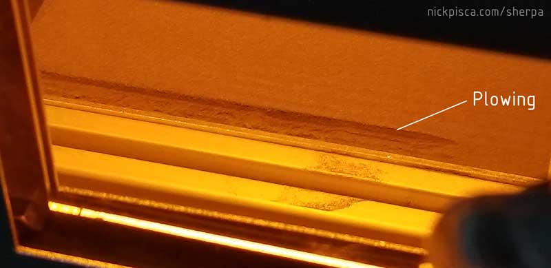
Once the surface has curled too high, the likelihood of Plowing is HIGH. In normal situations, the applicator takes a layer of powder from the supply bin, and drags it over the top of the sintered layer. If a model has curled though, that applicator fin might catch the curl and drag in across the bed. Depending on your STL layout, this could mean a complete destruction of your build. Thankfully, the Calibration Grid usually only fails in that particular row, and plowing is isolated to that row, so more test layers can be conducted.
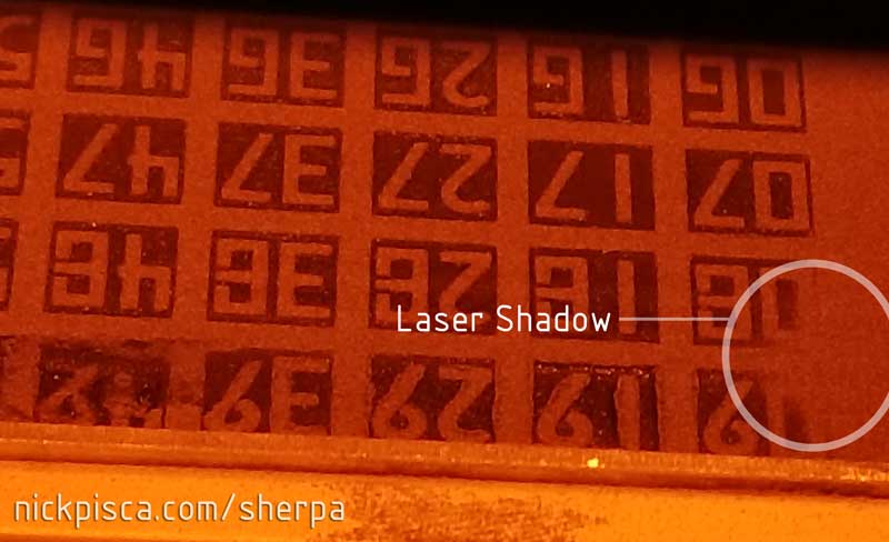
If you have an obstruction on your glass or laser porthole, then it will cast a shadow where the laser cannot reach the powder. This is really bad. The laser needs to be full capacity to properly sinter the powder. If you see a shadow on your Calibration Grid, try to remove or clean the obstruction. Lessened laser strength can also result in curling at the area.
On the side of this model, you can see a “plaque” of powder that has fused to the side of the model due to a hotspot on the bed. This hot area was the result of 174.0 deg C surface temperatures and a front blint that was angled too far toward the back of the machine. Try to use cooler temperatures to reduce the potential for plaque buildup.
Knowing all these features can help you understand the process for using this temperature calibration grid. The plan here is to optimize the laser sintering footprint to utilize the largest footprint without curling and delamination at the perimeter, and without fusing your center area solid.
The values at surface temperature are very minor. I have had some perimeter curling issues at temps as low as 173.3 deg C. However, I have had center fusing issues at 173.9 deg C. We are talking about a range of temperatures that can be as small as a few tenths of a degree difference. This is very tight to find the Goldilocks zone.
The nice thing about the Sintratec system is, they allow users to modify the surface and chamber temperatures in real time. That means if you see curling, you might have a quick chance to “send to the kit” some increased temperatures. Unfortunately, you cannot tell if your powder is fusing until you pull the model from the bed. So, the only workflow possible is starting with a lower temperature (like 172.0 deg C) and working your way up if you see curling. Once you get the model sintering where you like it, finish the build and do a proper cool down. Then example the center squares to ensure you didn’t melt them into oblivion.
Here is a video of me narrating my real time parameter modifications. When you get to the timelapse portion of the video, you will see the actual builds that I was using to calibrate my temps.
With the squares wiped down, I examined each one and documented which had issues.

I colored the offending squares and returned to my parametric model to better illustrate the safe zones of my kit.
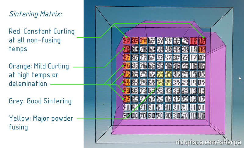
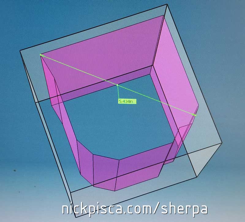
Using that color data, I produced a new solid that I considered to be a very safe volume for proper sintering. In the past, I was using a generic 9cm x 9cm x 11cm solid in Maya to ensure my model fit within the Sintratec guidelines. Now, with my new grid-generated solid, I can potentially SLS print objects that are up to 5 7/16″ long, and a greater size if that object was inserted diagonally on the Z.
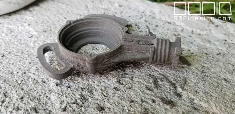
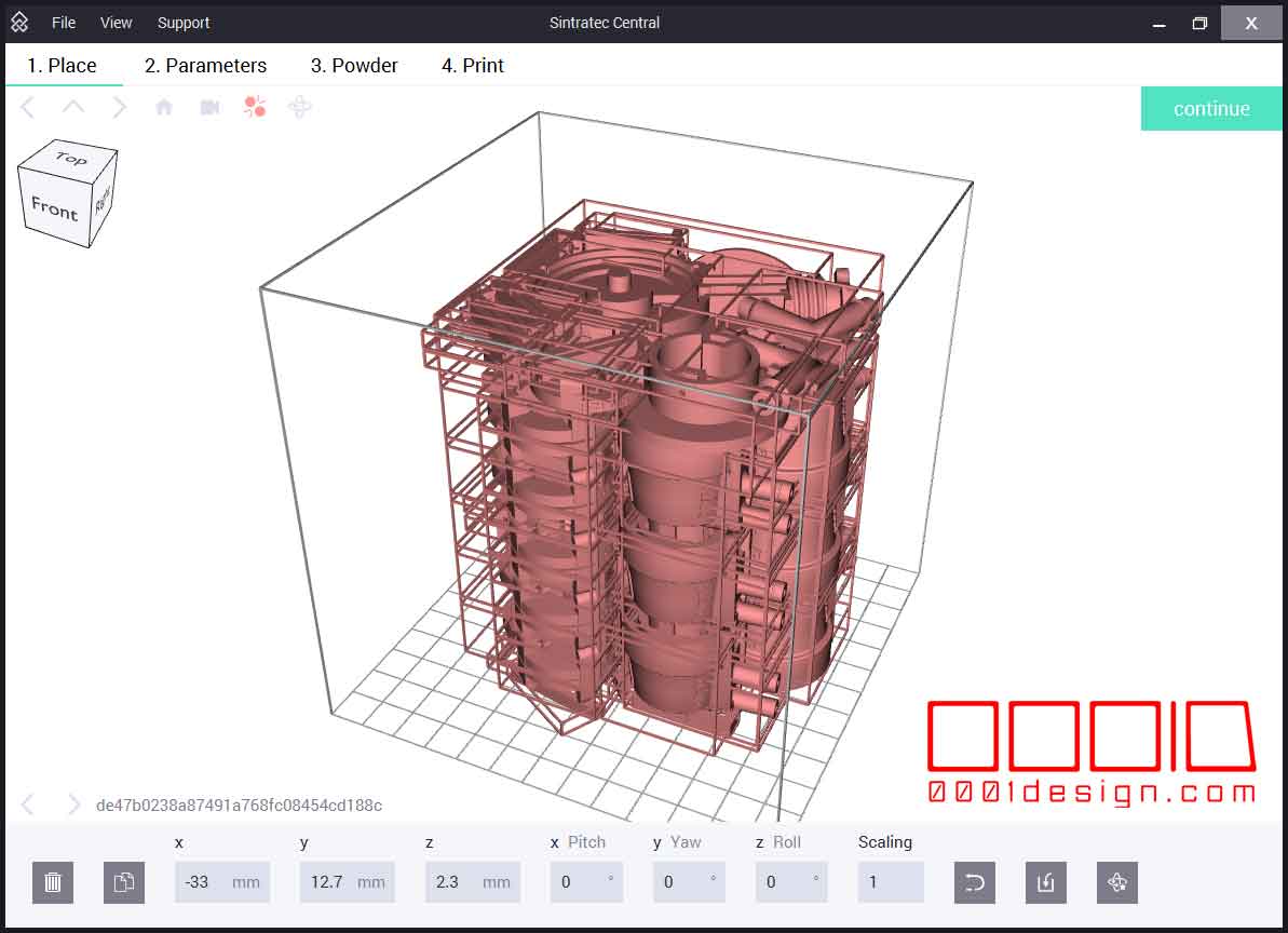
As I stated in a previous video, I was able to use this calibration grid boundary to produce our largest 3D print to date (by volume) without sintering issues:
In addition to this calibration, I have used this calibration grid to test the efficacy of sintering new, mixed, and old powder against each other. Also, I have tested it using lower temps to ensure no powder is fusing. Lastly, my future plans are to affix or create variable shaped blints to try and shade the center portion (44, 45, 54, 55) from one of the side IR lamps. I hope that by shading the middle, I might be able to maintain a 174.0 deg C surface temp, without the risk of the center squares turning into goo. Higher temps mean I can really push the footprint to the extents of the bed without worrying all night that my machine will be busted in the morning.

Recent Comments