
As we gain confidence in the power of this Sintratec Kit, we are attempting larger and larger print jobs. There is a fine balance on what you can sinter with this device, because as you go further to the edge of the bed, the more likely it will curl. The more likely it will curl, the more likely it will catch on your applicator fin, and potentially catastrophically pull your whole print out of the bed and ruin the whole build.
To counter curling, Sintratec and 3D Chimera recommends increasing the surface temp. The more heat you apply to the surface, the more likely your perimeter will sinter well. Attention! Any surface temps over 175 deg C will turn your powder into a brick! So, there is a “Goldielocks zone,” where you can get the maximum potential sintering footprint, but not fuse all your powder and models together.
A few days ago, we successfully got a great bunch of STL’s (approx 25 separate models) at some mild surface temps: (172.2 deg C). Check out the video here:
I liked what I got from that build, so I decided to push the sinter-able footprint to the limit. In a future post, I’ll detail how I was able to “Super-fine” calibrate my Sintratec Machine using a “Custom Calibration Grid.” This video shows the output of one of my tests (I think I did 5 or 6 of them, IIRC), and it really lets you calibrate the surface temps while identifying areas of poor sintering, laser shadows, curling, plowing, and powder fusion:
Like I said, I’ll have a much more in depth video/article detailing the Superfine Calibration Grid process, and how I got it all setup.
Using the information from my grid testing, I was able to find a “safe zone” volume that wouldn’t experience curling at 173.9 deg C. I know that is really high temp, but I wanted to test it regardless. I’ll have pictures of this “safe zone” volume in the future article.
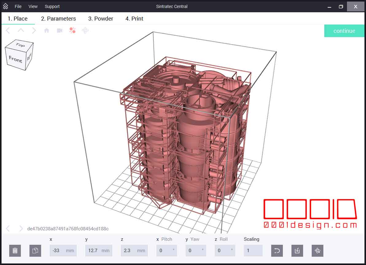
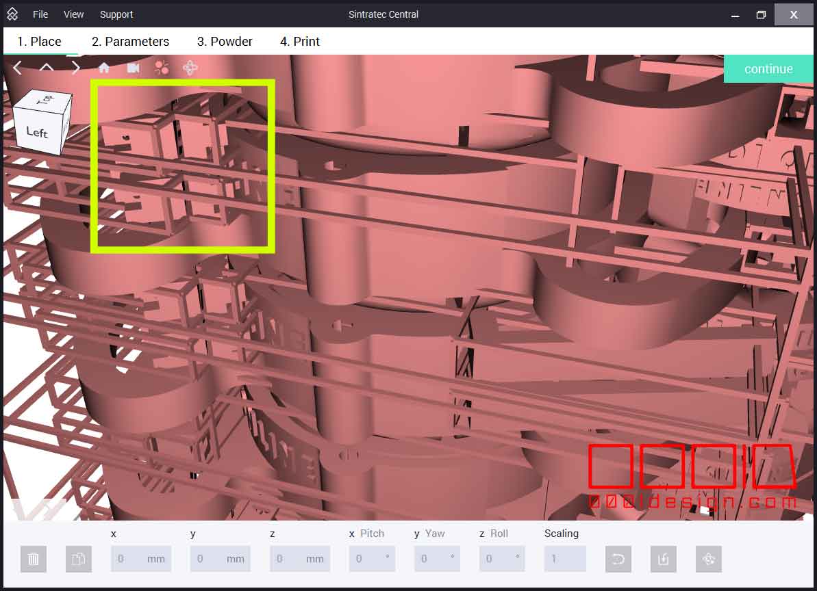
Then using my custom Maya MEL Sintratec Central exporter, I was able to bring in over 125 separate STL’s into Sintratec Central for this 1100-layer build. This would be not only the largest potential build that I ever attempted, but it would be literally the maximum Z-Capacity that the Sintratec Kit could obtain.
Even though I had done extensive testing with my Calibration Grid, I wanted to hedge my bets. I put in extra STL’s models at the XY Plane to give me an immediate indication of potential curling at the extents of my STL collection. Not all STL’s lay on the XY Plane, so by putting a few of these camlinks on the outside, then as the first few layers sinter, I will know right away if that is a failure point in this particular build. (I don’t want to get 300 layers in to find out that my cap.stl is going to curl and ruin the entire build)
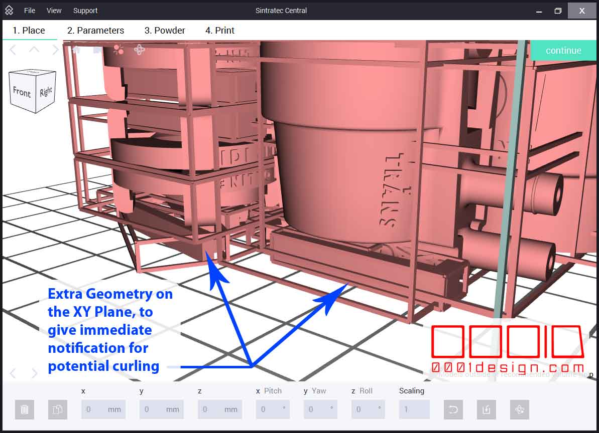
I’m currently working on a “footprint” MEL script that takes the perimeter of the entire build, and makes a 3-layer outline-solid on the XY Plane that will immediately tell the printer if the model will be good-to-go. I’ll post that once it’s functioning.
I let the build run from about 8pm to 8am, putting down over 800 layers. I did a 2-hour heat up prior to loading the model, and there was a 4 hour cool down afterwards, so overall, it was about a 18 hour process.
When I got up in the morning, the SLS Printer was working fine, but around 7am I noticed a small flap of plastic sticking up out of the powder on the far right side, near the 92 or 93 square. Maybe there was curling, IDK. After about a half hour of sintering, a bit of powder clung to the applicator fin. Then 2 more clumps adhered as well. They grew too large to be ignored and I skipped to “forced cool down” to preserve the existing models in the job. Using the Sintratec Central sintering layer image, I did wait for one of the larger STL’s to finish before killing the job.

Here is a picture of the clump of plastic that was causing the deepest line.
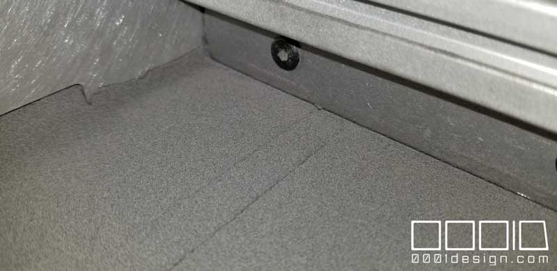
Depending on your end use, lines in the application may not be a problem for you. But I need my housings to be very accurate, so I stopped it from sintering more layers with the line in the project. Depending how large the line is, it can show up on your final print. So its up to you to abort or keep going.
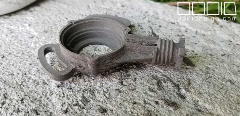
Here is the video of me pulling the models out of the build. Really amazing stuff. Thanks to the precision of this SLS machine, you can nest in dozens of STL files.
After investigating the print, I think I found the flap issue. There was an STL near the 92 square that delaminated and curled up. Each pass would touch that flap, and the heat of the surface would make the flap kind of gooey. After a few dozen passes, like an icicle, it accumulated enough gunk on the fin to cause a small line. Eventually, that line would grow deeper and deeper as the gunk built up.
I think in future builds, I’m going to remove that STL, or move it further to the right if possible. It is about a half centimeter from the edge, which is technically in the “sketchy” zone. But it should be printable because it is not in the 1cm margin that Sintratec recommends not occupying.
Due to the high temps, I did get some plaque on three of my models located on the 44, 45, 54, and 55 areas, which did require some scraping.
Thankfully, the plaque wasn’t that bad, and a metal brush and dental pick fixed that up. I’ll bring the temps down a bit to 173.3 deg C and make sure my perimeter areas are not curling before attempting another 1100-layer build.
Overall, even with all the issues, it was a successful build. I got over 100 models out of this aborted job, and it gave me a lot of information on how I can get even more out of my Sintratec Kit SLS Printer.

Recent Comments