
![[Video] Figuring out an STL Export/Import Workflow from Maya to Sintratec Central](https://www.nickpisca.com/sherpa/wp-content/uploads/2019/05/20190506_bypasstitle.jpg)
A brief recap on my recent progress with the Sintratec Kit. A few days ago, I tried to print a massive single file STL that contained several STL’s.
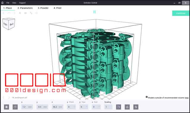
We are not sure just yet, but we have a theory that the massive STL file is leading to some Outline-and-Hatch mismatching after long stretches of sintering. See below:

Also, I had a bit of curling on the corners of my sintering platform, so I decided to chamfer my corners and use a 10cm x 10cm x 11cm bounding box for my design volume. I’ll increase that margin once I get more hours of sintering under my belt.
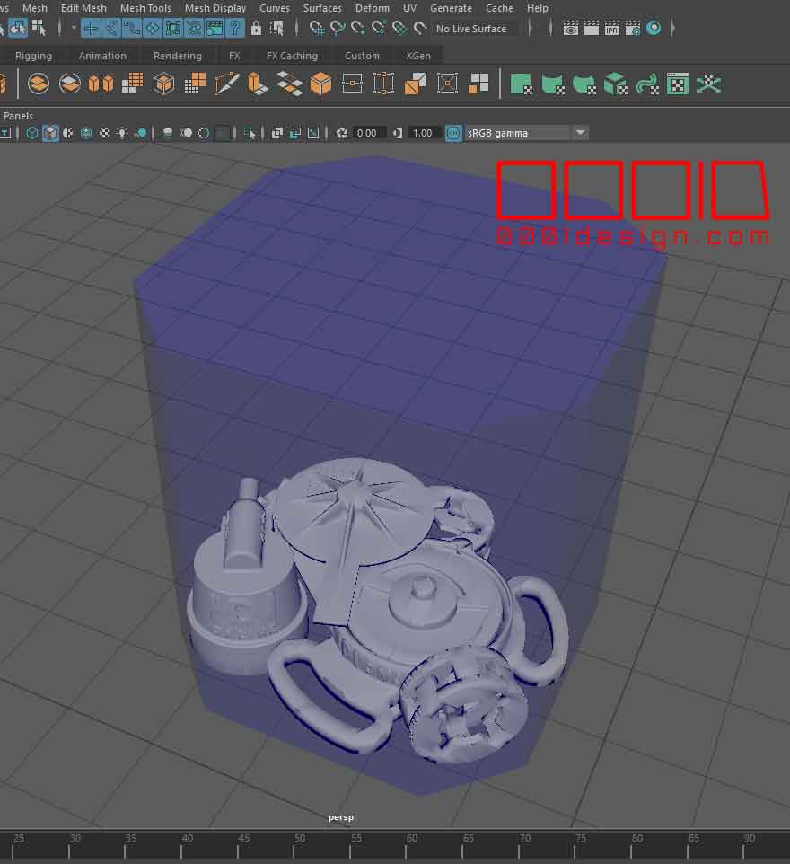
Here’s my latest bounding box volume. (The mesh designates 1cm squares):
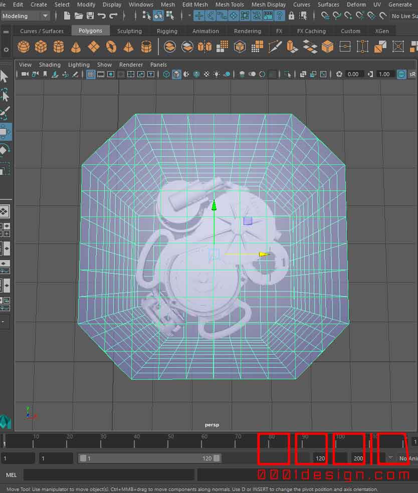
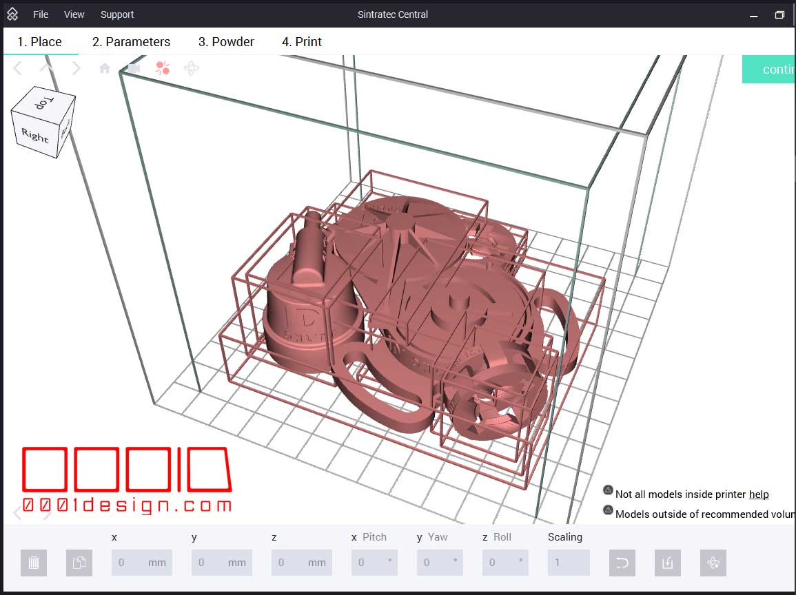
I put in a more reasonable testing collection at the base of my bounding volume. In the end, I will have dozens or hundreds more models, but just for this situation, I’ll focus on a small quantity.
Now, Sintratec can take in any STL files, whether they are one continuous mesh or a combination of individual meshes. The problem with combining meshes into one big STL file is, the sintering process burns all the outlines first, then fills in the hatching in one big pass. If you have individual meshes imported, then each profile is sintered, with its respective hatch. I think that will resolve my hatch-outline mismatch, but we won’t know until I do more testing. The other problem could be my galvos.
Sintratec Central allows for the instant drag-and-drop of STL files into one setup, so at least I don’t have to write a batch import script. The Sintratec Central API’s are not exposed anyway, so that wouldn’t be an option regardless.
Once you drop in a bunch of individual STL’s, it automatically places them scattered through the space. Pretty much the worst case scenario.
When you pick an object, the icons on the bottom become exposed, and you can select a useful tool called “Reset Part to STL Coordinates.” This will move and rotate that particular STL to the original XYZ location and original orientation as wherever you modeled it, like in Maya, Rhino, CATIA, etc.
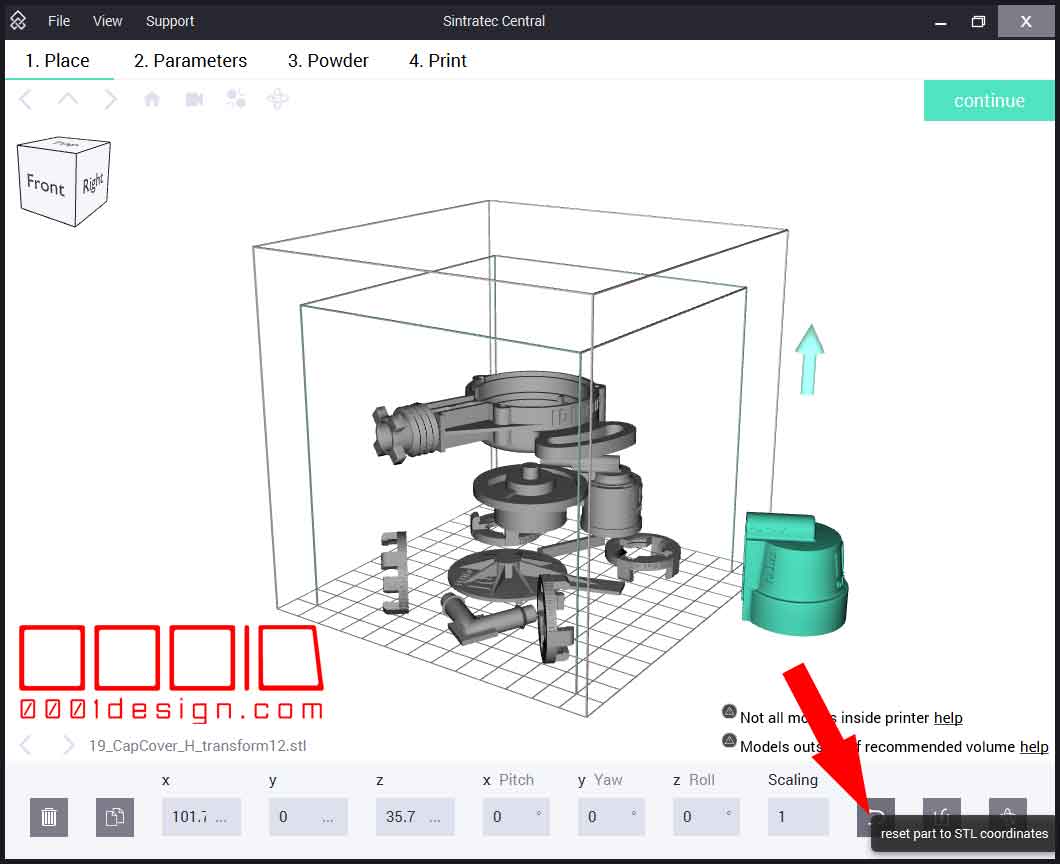
Well, not necessarily. It will place the STL at the proper X-coordinate, Y-coordinate, Pitch angle, and Yaw angle, but it WON’T place it on the proper Z-coordinate or Roll angle. This was extraordinarily frustrating.
After a good half day of tinkering around on these platforms (Maya and Sintratec Central), I finally figured out the problem. I made sure that all my pivot values for each Maya mesh were oriented based on the origin. Then I made sure that my Maya STL export values were set to the origin as well. Sometimes Maya uses the Center Pivot info, so cancel that out when you export from Maya to STL.
Next, I figured out that Sintratec Central was messing up the Z and Roll values. The Z value was negative than what it was supposed to be, and the Roll value was 180 degrees from regular. Since I was making a MEL plugin to export my STL files from Maya (I got a little bored exporting these one at a time), I added some reverse Z- and Roll-coordinates immediately prior to the export command, which forced the geometry to come into Sintratec Central backwards, which once I click “Reset Part to STL Coordinates,” it puts it in the right height and orientation.
FINALLY!!!! That was frustrating.
So now with my spiffy new MEL STL Batch Exporter script (with custom orientation subroutine), I can single click export all my STL’s into a folder. I need an UI and other stuff, which I’ll do in the future, and I’ll post that utility to my website once done and tested.
Just when I thought I had it all worked out, I another road block to my rapid workflow. Turns out that you can’t select multiple STL’s in Sintratec Central and do the “Reset Part to STL Coordinates.” Sheesh. Here’s the greyed-out icon when nothing is selected:

Here’s the greyed-out icon when more than one object is selected:
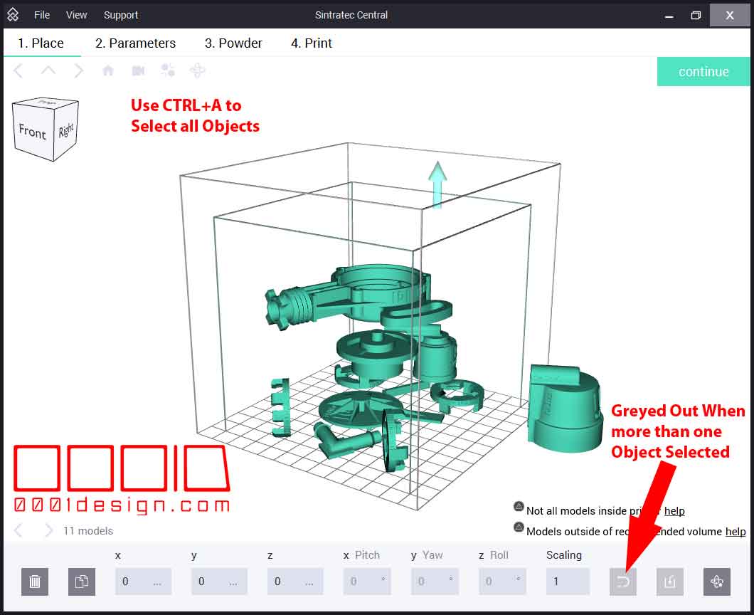
You gotta be kidding me. So in order to properly match my Maya model orientations and positions, I have manually click each STL and then click “Reset Part to STL Coordinates.” That’s going to take a while with hundreds of STL’s If a guy were to make chain mail or something that is interconnected together. Sintratec brags about how people can do interconnected geometries with this machine, due to the precision of the sintering laser, but how can a person feasibly do that when they have to spend hours manually clicking thousands of elements and the icon at the bottom? I hope they do a patch or hotfix to remedy this. Or at the very least, allow users to import all STL’s without their dumb automated scattering algorithm.
So, after manually clicking each object and the “Reset Part to STL Coordinates” button over and over and over and over, I got my geometry to situate EXACTLY as my Maya layout showed. Nice. Once it’s all set up, a user can just save this layout as an STEC file in the File > Save function.
Here’s a video of my gripe with the manual clicking. I’d seriously like that fixed as soon as possible.
My ultimate goal with the Maya MEL STL exporter is to make a plug-in in Maya that just generates the STEC file directly. The STEC file is just a compressed file containing all the STL’s from the scene, plus a simple json script file, with an encrypted “data” file. The data file likely just contains the X, Y, Z, Pitch, Yaw, and Roll info, along with the Scale value and a link to the UID on the STL (Sintratec removes the original mesh name and replaces it with a UID, which I also suspect is in that “data” file.)
I’m waiting for my USA Sintratec Rep (3D Chimera) to get back to me on if they have a stec file spec. Also, I wrote Sintratec Support, but I expect my reps to get better info. We’ll see.


Recent Comments