Recently, I had a correspondence with a good friend, Jayro88 from the FTE IDI Forum. He asked:
- As far as the GP harness, how did you go about it? Did you take all the looming off the stock harness and trace all the wires? I haven’t tracked the wires yet, is it a setup when you can undo a plug and remove the entire harness from the van, or is it wired with a bunch of other stuff?
It’s a good series of questions. I often overlook the things that are working really well in my van, because I’m often focusing on the latest thing I just fixed. Back in my Hypermax IDI Van Installation thread, I kind of glossed over the success of this rerouting of the bundle. Just to recap, I had to rerun this bundle because the up- and down-pipes, as well as the turbo housing itself would have burned up the stock layout of the bundle from the heat emanating off of it. Hypermax has a “suggested” routing of the bundle, but I did it differently. Here’s my response:
How I Redesigned the GP Harness:
The GP harness was one of the more difficult things to do, especially if I wanted to do it long lasting and somewhat elegant. In hindsight, I’m very pleased with the way I designed and implemented my bundle, especially considering all the times I have swapped my engines.
It was a long time ago, when I designed it, so I went back to my archives to figure out my design:
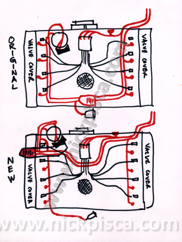
- “One of the most time consuming tasks was re-routing the glowplug harness assembly. Hypermax has a diagram that they consider a good plan for this. I read it, and figured I could enhance the design a little. Instead of one main glowplug harness bundle, I made two secondary branches that isolate the glowplug sockets for each side of the engine. Also, the driver’s-side secondary branch contains an extension wire for the oil pressure sensor. Here’s a drawing of what I came up with: (Note, I’m not posting Hypermax’s diagram because it’s their IP and they didn’t include it in their online instructions, but it does appear in the purchased kit. That leads me to believe that they don’t want it out on the net, so if you want to see a copy, you should contact them directly.)”
I do remember stripping off the stock wire loom and re wrapping everything. Also I re taped everything too. However, this wire wrapper was some cheapo stuff from Autozoo, and when I did the heads, I noticed that much of the loom had melted and deformed.
I wrote:
- “I redid the glowplug and sensor wiring harness while I had it out. Super clean now:”
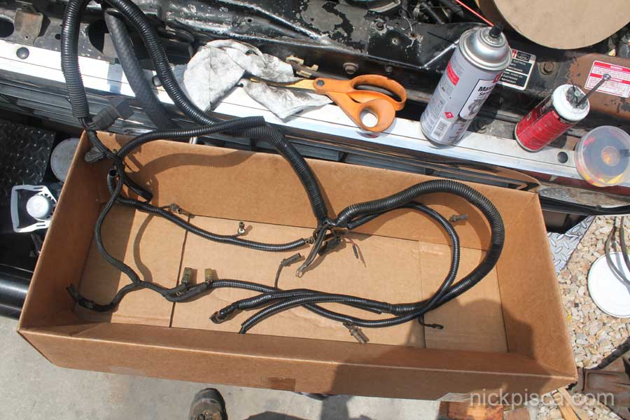
When I “redid” the harness, I should have mentioned that all I did was remove all the cheapo wrap, and put on highest temp rated wrap from McMaster Carr. That McMaster wrap has lasted perfectly, so I highly recommend it. Just use the search feature to narrow the type down to the 200+ deg wrap.
My van harness did have a plug (located near the heater fan) that theoretically allows the owner to unplug it from the van’s electrical system. When I first bought my van, I made the dumb mistake of unplugging it once to access the alternator or heater fan or something dumb like that. Why was that dumb? The bundle was never separated from the stock wiring before, and they had semi fused together. By prying them apart, I inadvertently damaged the connectors. When I reassembled the connectors, and then fired up the engine, the two yellow wires (providing current to the GPs) started smoking bad. The guys on the FTE forum told me to bypass the connector for those 2 wires, with small sections of low-gauge wire, and if I ever wanted to separate the bundle from the van, I’d have to cut those two wires.
So for these old engines, I’d recommend not unplugging your bundle from the vehicle, because you might not be able to reconnect the bundle without corrosion or connection issues. That’s why all my bundle upgrade photos are the bundle still situated in the engine bay, with the bundle draped over the bumper or battery area.
That was the end of the email. I neglected to mention that ever since I upgraded to the R&D Stage 1 filter setup on the rails, I basically taped up most of the sensor connectors in the bundle and put them out of use on the side of the engine. The only sensors that are connected, are the oil pressure sender and block temp sensor. All other sensors, like the fuel filter sensors and the coolant sensor switch, are disconnected and their respective wires are packed with dipole grease and carefully wrapped in high-temp electrical tape. I kept them in this cocoon just in case I feel the urge to reimplement them back to stock. However, due to the lack of decent replacement parts, I’m unable to find a functioning Coolant Sensor Switch and I’ve already rid myself of most of my spare stock filter heads. I’m going all in now.
No warranty. You are responsible for your vehicle. For novelty use only. Not responsible for anything or anyone. Not responsible for damage to your vehicle, you, or anyone or anything.
Copyright 2000-2018 Nick Pisca 0001D LLC