VRV Quick Installation Guide: (Quick Instructions are in dark green text)
If you want to quickly install a VRV (Vacuum Regulator Valve), read the following paragraphs.
The VRV installs on the driver’s side of the Injector Pump (IP) on the top of the engine. It rotates with the throttle to convert vacuum pressure for the transmission. It’s a simple installation process, but I have a few things you’ll need to check out first.
Here’s what your Injector Pump and VRV should look like once installed: (this is the end goal)
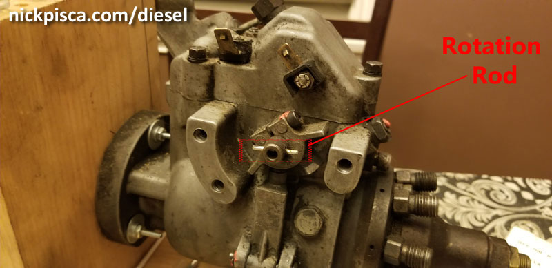
Before you install it, check to make sure your Injector Pump has a pin or rod like this: (It kind of looks like a nail. If you don’t have this, contact us.)
Next is the installation:
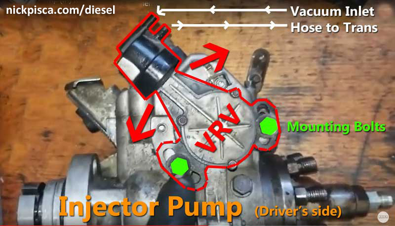
Here’s an image of an Injector Pump laying on my workbench, with the VRV installed on the side.
In green, there are two mounting bolts. That’s it. Slide the VRV on the side of the IP, and tighten the bolts down. Make sure to install the VRV so that the rod can rotate the VRV camshaft.
Then connect the vacuum hoses. Most Fords had a special VRV top connector like this:
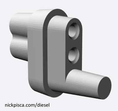
If you don’t have one of these, it’s no big deal. You can use regular vacuum hose from your typical autoparts store. (Look at the image below to make sure the top hose connects to the Vacuum manifold, and the bottom hose goes to the transmission modulator, shown in white text.)
Adjusting the VRV Shift Points.
Take the truck for a drive and see how it shifts.
If it shifts too soon or too late for your liking, stop the truck, turn off the engine, unscrew the mounting bolts a little bit to loosen up the VRV, rotate the to the front or rear of the truck a few degrees, and tighten the VRV back down again. The red arrows in the image below show how it rotates.
Keep adjusting the rotation of the VRV until you like where it shifts. That concludes installation calibration. If things are still not working correctly, please contact us. If things are fine, then you are done with this webpage.
What if your vehicle never had a VRV before?
Some people (like someone doing a Diesel swap) may never have had a VRV on their IP before. For most Diesel swap projects, you won’t find all the connectors and supplementary parts for the VRV installation. IDI Online does have a small inventory of vacuum system parts, and contact us for what you need.
Connect the vacuum connector to the top of the VRV and you are done with the installation. If you don’t have the connector, the top VRV hose-bib is for the vacuum supply hose. Find your vacuum manifold (should look like this in a truck:)

Install a vacuum hose from this manifold to the VRV top bib.
Then place a vacuum hose from the bottom VRV bib to the C6 Transmission Modulator. That is located at the back of the transmission under the truck.
If you don’t know where your modulator is, this video shows a guy removing his. It looks like a little cylinder on the end of the transmission. (since your PO probably didn’t maintain his modulator, you might want to inspect it for damage or gunk).
That would conclude the vacuum hose installation.
More Advanced Calibration, Servicing, and Testing (mainly for mechanics and technicians):
We’ve collected any C6 VRV (Vacuum Regulator Valve) information from the service manuals and internet that we could find. Many of the VRV servicing explanations on the internet are messed up, and they need some cleaning or revising. Here’s a collection of data we’ve cleaned up in a more readable format, with complete citations at the bottom of the article.
If you are looking for VRV replacement part(s), Click Here.
Disclaimer: You are responsible for your vehicle and actions. This article is for educational use only. IDI Online is not responsible for anything or anyone. Not responsible for damage to your vehicle, you, or anyone or anything. Take your vehicles to a professional when servicing the transmission, engine, and its components.
From the 1988 Ford Service Manual (citations at the end of the article):
- Emission Systems Required Maintenance
Maintenance Schedule E – 7.3L Diesel Engine Equipped Vehicles Econoline and F-Series (Light Truck)
SERVICE INTERVALS: Perform at 6 months or the distance shown whichever comes first.
Check Vacuum Regulator and Adjust If Required (Automatic Transmission Only):- 5000 miles (8000 km)
- 15000 miles (24000 km)
- 30000 miles (48000 km)
- 45000 miles (72000 km)
- 60000 miles (96000 km)
- 75000 miles (120000 km)
- 90000 miles (144000 km)
- and every 15000 miles (24000 km) thereafter
- Vacuum Regulator Valve must be adjusted to specifications. Any setting outside the specified range may lead to transmission malfunction (Automatic Transmission Only).
Continued in the service manual….
- General Automatic Transmission Service
Control Pressure Test
C6
There are two methods of performing the control pressure test. One is to perform the test using the engine vacuum. The second method is to use a remote vacuum source such as the one provided in the distributor tester or a hand operated vacuum pump.Engine Vacuum Pressure
When the vacuum diaphragm unit is operating properly and the manual and downshift linkage is adjusted properly, all the transmission shifts (automatic and kickdown) should occur within the road speed limits listed in the Technical Service Bulletin-Special Specifications Issue.If the shifts do not occur within limits, or the transmission slips during shift point, use the following procedure to determine whether the engine, transmission, linkage, vacuum diaphragm unit or valve body is causing the condition. See Section 17-10 for 7.3L Diesel C6 application for (VRV) Vacuum Regulator Valve.
Also, the manual specifies a particular sized block to aide in the VRV calibration process:
- SPECIAL SERVICE TOOLS:
T83T-7B200-AH: VRV (Vacuum Regulator Valve) Adjustment Gage Block – C6
Further in the manual, they explain the particulars of the VRV and C6:
-
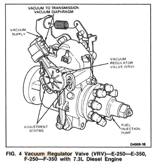
FIG. 4 Vacuum Regulator Valve (VRV) – E-250-E-350, F-250-F-350 with 7.3L Diesel Engine. 1988 Ford Truck Shop Manual, Vol. A
C6 Automatic Transmission
Section 17-10 C6 Automatic Transmission
Vehicle Application
Applies to E-150 Through E-350, F-150 Through F-350 (4×2), (4×4) and Bronco Model Trucks.Vacuum Regulator Valve (VRV)
The Vacuum Regulator Valve (VRV) is used on E-250-E-350 and F-250-F-350 vehicles equipped with 7.3L diesel engines.On 7.3L diesel engine trucks equipped with a C-6 automatic transmission a Vacuum Regulator Valve (VRV) is incorporated to provide a vacuum signal which is proportional to the throttle position to the vacuum diaphragm of the transmission. The VRV is necessary to provide a vacuum signal to the C-6 transmission because the diesel engine has no vacuum. The VRV is bolted to the fuel injection pump and is actuated by the throttle lever.
A constant vacuum source is supplied to the VRV by an engine driven vacuum pump which also delivers vacuum to other accessories. The VRV regulates an output vacuum signal to the transmission’s vacuum diaphragm which is proportional to the throttle position. As the throttle is opened, the regulated vacuum from the VRV drops.
Should a malfunction occur in the VRV, the valve will cause a 0 vacuum signal to be sent to the diaphragm which will cause delayed and harsh shifts to occur.
Anytime delayed or harsh up-shifts are encountered, the performance of the VRV should be checked prior to performing any transmission repairs. Should the VRV be replaced or the fuel injection pump be removed, the VRV must be adjusted to specifications.
ADJUSTMENTS
…On vehicles equipped with 7.3L Diesel Engines, the Vacuum Regulator Valve (VRV), which is located on the fuel injector pump must be properly adjusted to regulate vacuum to the transmission vacuum diaphragm…Vacuum Regulator Valve (VRV) Operational Check and Adjustment (Vehicles Equipped with 7.3L Diesel Engine only)
To check the VRV for proper operation and to adjust, the engine must not be running (TURNED OFF).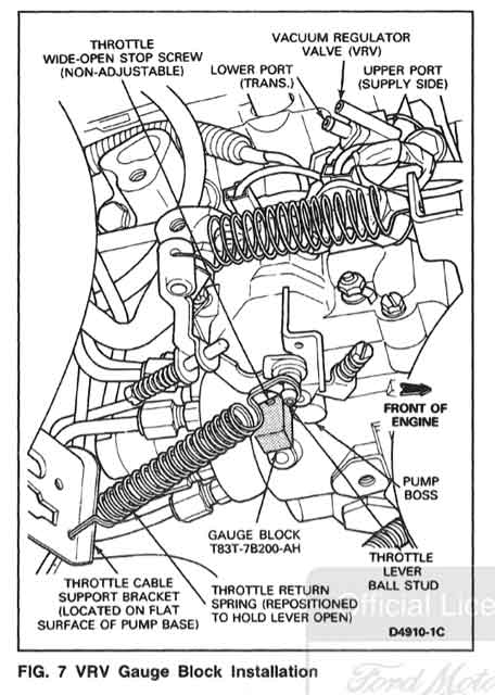
Fig. 7 VRV Gauge Block Installation. 1988 Ford Truck Shop Manual, Vol. A
1. Disconnect the two port vacuum connector from the VRV located on the left side of the fuel injection pump.
2. Remove the throttle cable from the throttle lever on the right side of the fuel injection pump.
3. Remove the throttle return spring. Install the end of the spring over the throttle lever ball stud and the other end over the throttle cable support bracket.
4. Attach a vacuum pump to the upper port of the VRV (vacuum supply side).
5. Attach a vacuum gauge to the lower port of the VRV, labeled TRANS on the VRV.
6. Apply 20 inches minimum of vacuum to the VRV and maintain. It will be necessary to cointually pump the vacuum up as it bleed off (this is normal). Cycle the throttle lever 5 times from idle to WOT with vacuum applied. Insert the guage block, T88T-7B200-AH (0.515 inch), between the pump boss and the throttle wide-open stop (Fig. 7). The throttle return spring (F-Series), as repositioned in step 3 below, will hold the throttle lever stop against the gauge block (Hold throttle lever open on Econoline by other means). The vacuum gauge attached to the lower port of the VRV should indicate 6-8 inches of vacuum. If the vacuum reading is not correct, adjust the VRV to achieve a reading of 7 inches (+/- .5) of vacuum.
7. To adjust, loosen the two adjustment screws that attach the VRV to the fuel injection pump (Fig 4). Rotate the VRV until the proper vacuum is obtained. Tighten the two adjusting screws to 8-10.5 N-m (75-90 in-lbs) when the proper vacuum reading is obtained. If the VRV can not be adjusted to obtain the proper vacuum, replace the VRV and repeat procedure from Step 3.
8. Remove the Gauge Block.
9. Reattach the throttle return spring and throttle cable.
10. Again apply 20 inches of vacuum to the VRV and while maintaining vacuum, cycle the throttle lever from idle to WOT 5 times. The vacuum gauge must indicate at least 13 inches (throttle at idle position). If the vacuum gauge indicates less than 13 inches the VRV must be replaced and the new VRV adjusted per the above procedures.
11. After making the check or adjustment, remove the vacuum pump and gauge from the VRV and reattach the vacuum connector.
12. Start engine and check throttle operation and check transmission shifts.
This procedure is rather straightforward, and when the procedures are followed strictly, it’s the best way of diagnosing the issues of a VRV on an IDI.
Further, in the glossary, they define “VACUUM REGULATOR” as “Provides constant vacuum output when vehicle is at idle from manifold. Switches to engine vacuum at off idle,” which clearly only pertains to the gasoline engine. The IDI engine has a dedicated vacuum pump to provide the requisite vacuum to the VRV and other vacuum-necessary components in the engine and cab. Also, the glossary defines “VRV (VACUUM REGULATOR VALVE)” as just a “Three port valve.” That’s quite an understatement.
From workshop-manuals.com and Oilburners IDI tech forum (citations at the end of the article), the information was surrounded by faulty HTML flags and other meta data that cluttered up the procedure from the 1983 service manual. Also, the images were not properly linked on the forum, so I searched the net to find the actual images from that procedure. We cleaned up the information and tried to keep it as close as possible to the original HTML documentation:
| 3. | Check adjustment of Vacuum Regulator Valve (VRV) (automatic transmissions only). Refer to Figures 22 and 23. On a 6.9L diesel engine equipped truck with C6 automatic transmission, a VRV provides a vacuum signal which is proportional to the throttle position, to the transmission vacuum diaphragm. To check the VRV for proper operation and adjustment, the engine must not be running. |
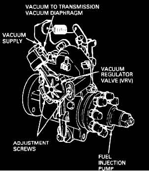
Figure 22 – Article 87-10-21. F 350 4WD Pickup V8-6.9L DSL (1983). workshop-manuals.com
| a. | Disconnect the two-port vacuum connector from the VRV located on the left side of fuel injection pump, Figure 22. |
| b. | Remove throttle cable from throttle lever on right side of fuel injection pump. |
| c. | Remove throttle return spring. Install end of spring over throttle lever ball stud and other end over throttle cable support bracket. |
| d. | Attach a vacuum pump with gauge to upper port of VRV (vacuum supply side). |
| e. | Attach a vacuum gauge to lower port of VRV (labeled TRANS on VRV). |
| f. | Apply 20 inches minimum of vacuum to VRV and maintain. It will be necessary to pump vacuum up as it bleeds off. CYCLE THROTTLE LEVER FIVE (5) TIMES FROM IDLE TO WIDE OPEN THROTTLE (WOT) WITH VACUUM APPLIED. |
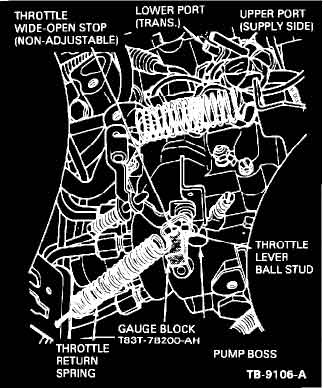
Figure 23 – Article 87-10-21. F 350 4WD Pickup V8-6.9L DSL (1983). workshop-manuals.com
Insert gauge block, T83T-7B200-AH (0.515 inch), between pump boss and throttle wide-open stop, Figure 23. The throttle return spring, as re-positioned in Step C. above, will hold throttle lever stop against gauge block.
THE VACUUM GAUGE ATTACHED TO LOWER PORT OF THE VRV SHOULD INDICATE 6-8 INCHES VACUUM. IF VACUUM READING IS WRONG, ADJUST VRV TO OBTAIN READING OF SEVEN (7) INCHES OF VACUUM.
| g. | To adjust, loosen the two (2) screws that attach VRV to fuel injection pump, Figure 22. Rotate VRV until proper vacuum is obtained. When you get proper vacuum reading, tighten the two (2) screws to 75-90 in.lbs. (8-10.5 N-m). If VRV cannot be adjusted to get proper vacuum, replace the VRV and repeat this procedure starting at Step D. |
| h. | Remove gauge block. |
| i. | Reattach throttle return spring and throttle cable. |
| j. | Apply 20 inches of vacuum to the VRV and WHILE MAINTAINING VACUUM, CYCLE THROTTLE LEVER FROM IDLE TO WOT FIVE (5) TIMES. The vacuum gauge must indicate at least 13 inches with throttle at idle position. If vacuum gauge indicates less than 13 inches, the VRV must be replaced and the new VRV adjusted per the above procedure. |
| k. | After making the check or adjustment, remove vacuum pump and gauge from VRV and reattach vacuum connector. |
| l. | Start engine. Check throttle operation and check transmission shifts. |
The forum tech thread continues with another explanation of the VRV testing process. Their images are dead links, but they should likely coincide with the images mentioned above.
VACUUM REGULATOR VALVE ADJUST
NOTE: During the check and adjustment procedure, the engine must not be operating.
- Disconnect two port vacuum connector from vacuum regulator valve located on the left side of the fuel injection pump.
- Disconnect throttle cable from throttle lever.
- Remove throttle return spring. Install end of spring over throttle lever ball stud and other end of spring over throttle cable support bracket.
- Connect a suitable vacuum pump to the upper port of the vacuum regulator valve (vacuum supply side).
- Connect a suitable vacuum gauge to lower port of vacuum regulator valve labeled TRANS.
- Apply and maintain 20 in Hg of vacuum to the vacuum regulator valve. It will be necessary to pump the vacuum up as it bleeds off. Cycle the throttle lever 5 times from idle to the wide open throttle position with vacuum applied.
Insert gauge block No. T83T-7B200-AH (0.515 in) between pump boss and throttle wide open stop. The throttle return spring as repositioned previously, will hold the throttle lever stop against the gauge block tool. The vacuum gauge should indicate 6-8 in Hg of vacuum. If reading obtained is not as specified, adjust vacuum regulator valve as follows:
-
- Loosen two adjustment screws attaching vacuum regulator valve to the fuel injection pump.
- Rotate vacuum regulator valve until correct vacuum reading is obtained, then torque the two adjustment screws to 75-90 in lbs .
- If vacuum regulator valve cannot be adjusted, replace vacuum regulator valve and repeat adjustment procedure.
- Remove gauge block tool.
- Connect throttle return spring and throttle cable.
- Apply 20 in Hg of vacuum to the vacuum regulator valve and while maintaining vacuum, cycle throttle lever from idle to the wide open throttle position 5 times . The vacuum gauge should indicate at least 13 in Hg(throttle at idle position).
- If vacuum gauge indicates less than 13 in Hg the vacuum regulator valve must be replaced and the new valve adjusted.
- After necessary adjustment procedure has been completed, remove vacuum pump and gauge from vacuum regulator valve. Reconnect vacuum connector.
- Start engine and check operation of throttle. Check transmission shifts.
The thread ends with a reference to “© 2013 ALLDATA LLC. All rights reserved. Terms and Conditions” but no link or citation was left to allow for a direct reference. If anyone knows from which service manual or website this sequence was extracted, please make a comment below and we’ll make sure to include it in our bibliography below.
Also, of course, there is an amateur, but very decent video of how to test this on Youtube. I think this is a pretty reasonable visual on the process, however, like all online videos, improper education and implementation of VRV pressures and installation can lead to injector pump, engine, and transmission issues. Improper vacuum pressure at the Transmission Diaphragm can, over time, lead to premature C6 Transmission issues. Regardless, for educational purposes, this video explains the VRV testing process:
(Ford Part Nos. F0TP-7B200-AA, F0TP-7B200-A, E7TA-7B200-AA, E7TA-7B200-AB, E7TA-7B200-AC, E8TP-7B200-AA, FOTP-AA or International Part No. 1801361c7)
No warranty. You are responsible for your vehicle. For educational use only. Not responsible for anything or anyone. Not responsible for damage to your vehicle, you, or anyone or anything. Have professionals service your vehicle.
For more information on the IDI VRV Rebuild/Replacement Project, visit this article:
Citations:
1988-1993 Engine Service Manual Supplement 7.3 Liter Diesel Engine.
1988 Ford Truck Shop Manual, Vol. A: Bronco Econoline F150-350 Super Duty.
- Maintenance 10-02-6
- General Automatic Transmission Service 17-01-6, 17-01-7, 17-01-37, 17-10-1, 17-10-2, 17-10-3, 17-10-4
- Glossary of Terms, Emissions Related Components
https://workshop-manuals.com/ford/f_350_4wd_pickup/v8-6.9l_dsl/powertrain_management/fuel_delivery_and_air_induction/throttle_cable/linkage/component_information/technical_service_bulletins/all_technical_service_bulletins_for_throttle_cable/linkage/871021/may/87/diesel_engine_supplemental_diagnostic_tips/page_2013/
https://www.oilburners.net/threads/vrv-adjustment.64130/
https://www.ford-trucks.com/forums/412166-vrv-valve-adjustment.html