I got a ’94 IDI non-turbo van engine that had some weird squeak when it ran. A different shop ripped it apart and found the 8th cylinder delaying when the flywheel was turned. I also had an ’88 IDI Hypermax turbo van engine that might have a cracked block. Here are the photos showcasing the tear down of the ’88 IDI.
I mounted the ’88 on the stand and started ripping it apart.
Here’s the status of the engine:
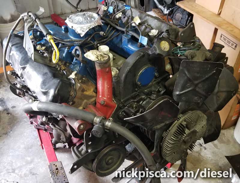
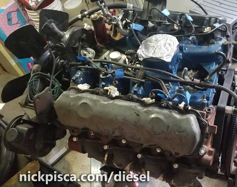
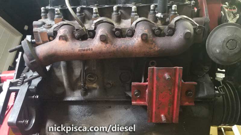
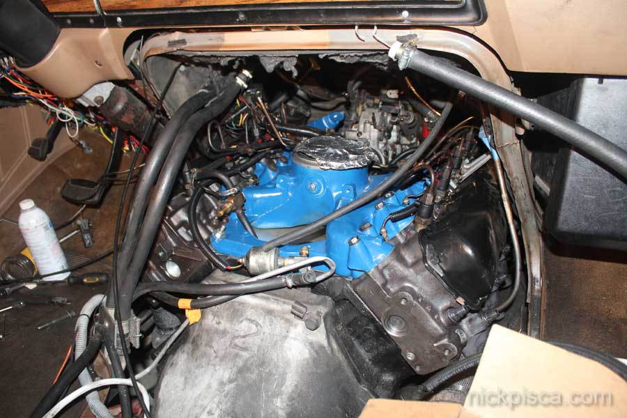
Photo of this engine in the van engine bay, looking through the doghouse.
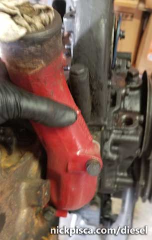
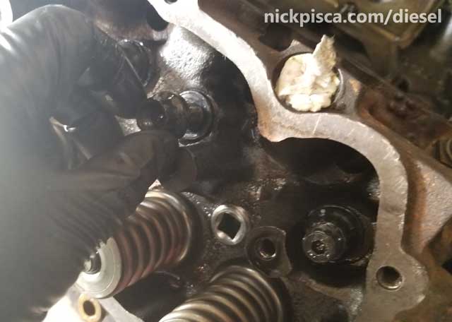
Pretty standard. Probably the only thing that should would spark anyone’s interest is where the CDR is. One the Hypermax, they remove the CDR from the intake and valley pan, and replace it with a stopper in the back of the intake manifold. You can see the Hypermax stopper in the image (taken in at the head gasket job) to the right:
Also, the injectors were already taken out and archived in a box. Before taking the IP off, I undid the injector lines. In hindsight, I should have left them attached; the bottom two injector lines are notoriously difficult to refasten, so I should have left them in place. Oh well. The IP is easy to remove, just undo the gear house front plate, and undo the three 5/16″ 12-point bolts on the inside.
 Then I removed the 9/16″ nuts on the back side of the gear housing. With the nuts removed, the IP slides straight back toward the rear of the engine.
Oh, I forgot to mention I drained the engine oil and pulled the oil filter before documenting this.
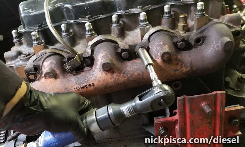
I ripped off the exhaust manifolds
Next I removed my spiffy ARP stud aeronautical covers from McMaster Carr. I highly recommend using these to protect the ends of your head studs.
Next, I unbolted the Intake Manifold.
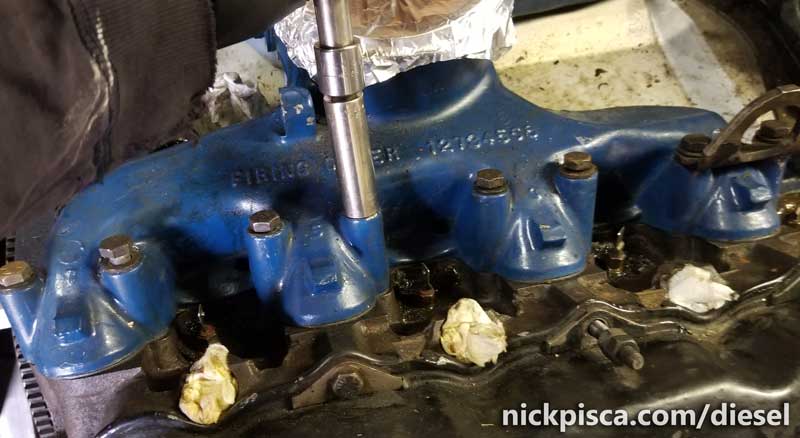
I marked down the lengths of the intake bolts so I could remember which went where. But if I forgot, I could always just look at the height of the intake holes, and get the jist of their locations.
Next is the valve covers. For the most part, VC bolts are the same, except for studs used to hold stuff. On the van, there are things like the oil and tranny dipstick tubes that are fastened to a bracket connected the passenger side VC studs. And every vehicle type is different.
I pulled the oil dipstick tube out. It had connected to an exhaust manifold stud, but the tube itself had a seal that held it in place. I just pulled it straight out and cleaned up the inlet.
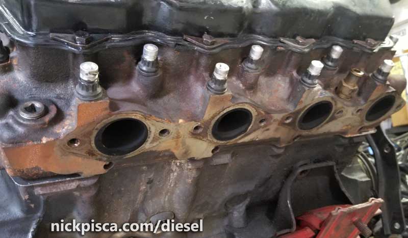
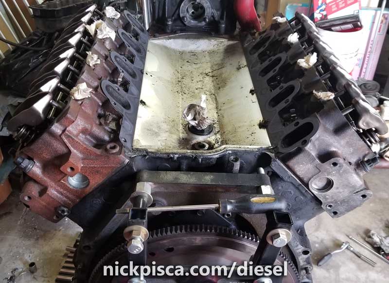
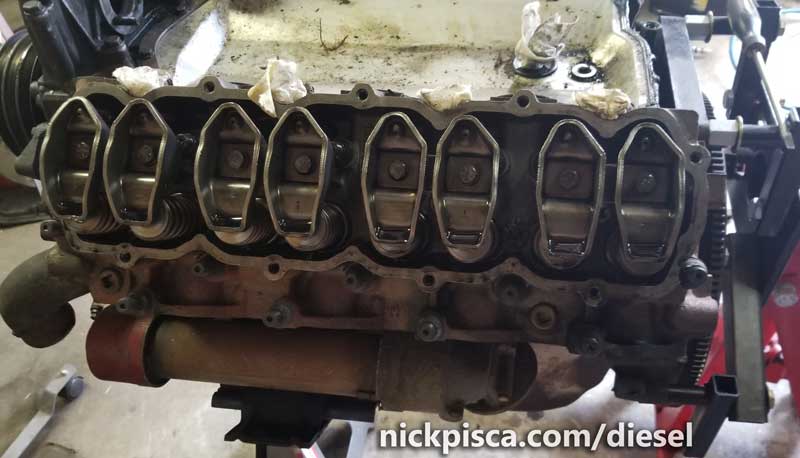
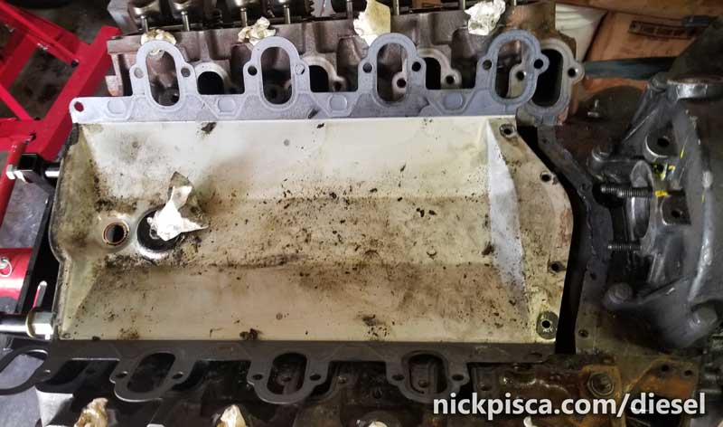
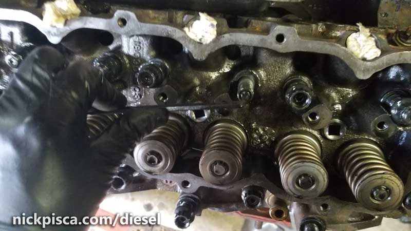
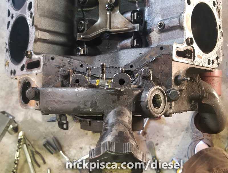
Here’s the condition of the engine with the intake, VC’s, and EM’s off.
The rockers look ok.
I pulled off the t-stat housing. Ugh. I’ve done that a gazillion times when I had the oil-in-coolant issue. I tossed the t-stat inside it, because I’m confident its coated in oil.
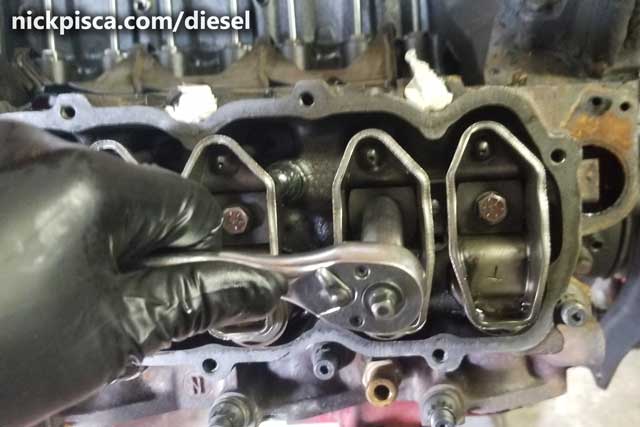
I then carefully pulled the valley pan. Most people throw these away because they are such thin metal, it is hard to remove them without permanent damage to them. I want to reuse this one at some point, so I’m super careful to extract if.
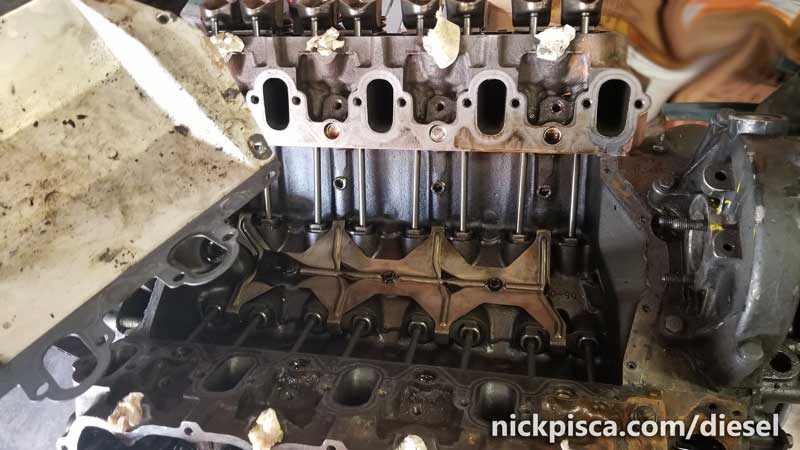
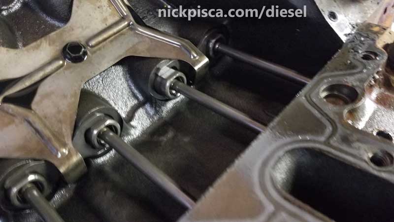
Next I pulled the rockers out pair-by-pair, marked them, and carefully stored them in a box for future reinstallation.
I pulled the push rods, labeled them, and skewered them in a box to make sure they didn’t get mixed up.
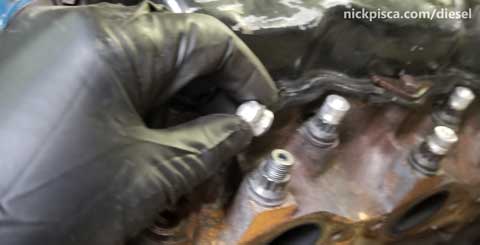
Next, I unscrewed the head stud nuts.
and the studs…
I cleaned and stored my ARP studs. I have been told I can reuse these expensive fasteners up to three times, so I’m not going to waste them.
Once the nuts and studs were gone, I used a screwdriver on the side to pry up the heads off the gaskets. I only pried it from the metal OUTSIDE of the gasket mating surfaces. Prying on the block or head decks will ruin them for good.
One of the studs was a PITA. It took some elbow grease to extract.
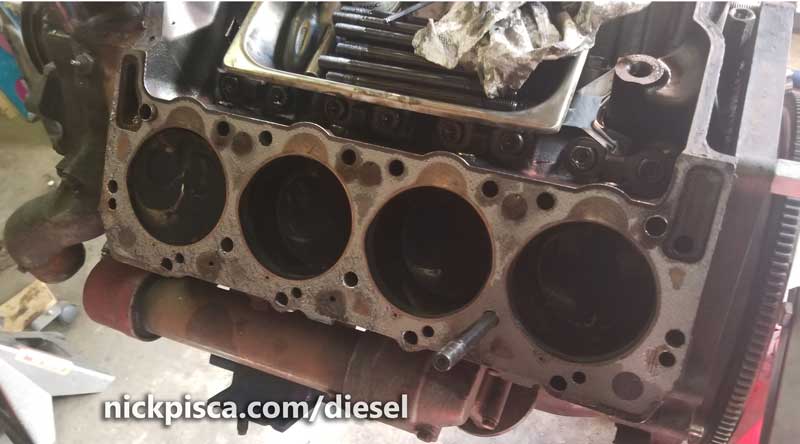
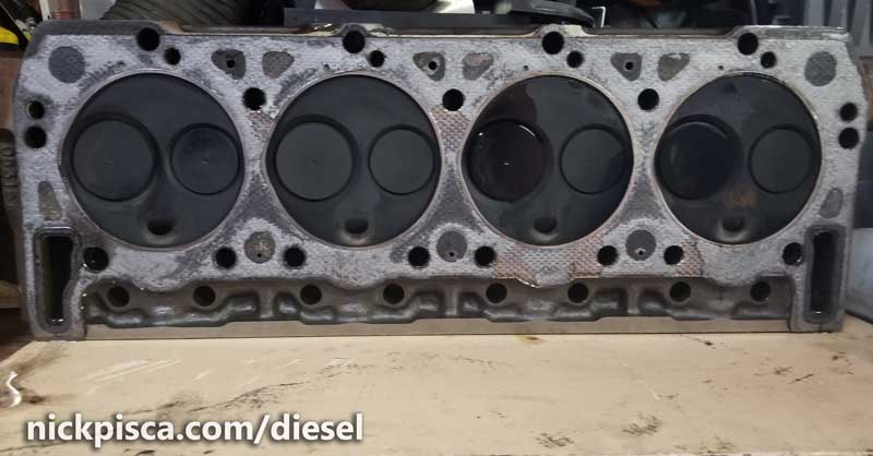
The condition of the heads looked pretty good. (I would later find out that the HG surface came off without any real work or scraping)
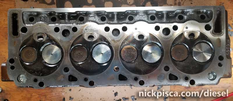
Picture from a few days later after I cleaned off the head gasket material from the cylinder head deck.
Then I moved on to the waterpump. There are many bolts in this area and on the front plate. If you forgot which bolts go where, you can find the waterpump bolt information on this brilliant thread.
Next, I removed the main pulley and harmonic balancer.
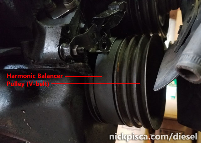
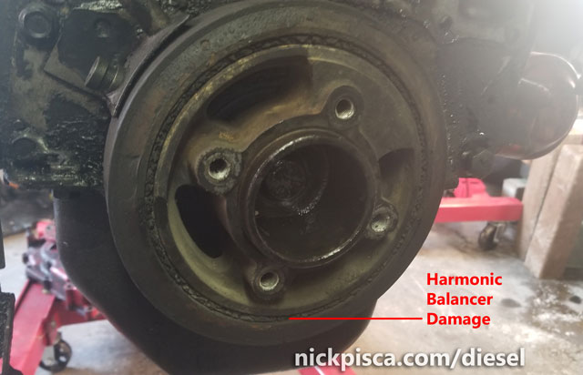
There is a lot more detailed information on the removal (and reinstallation) of the Harmonic Balancer here:
6.9 / 7.3 IDI Harmonic Balancer (Vibration Damper) Replacement Process
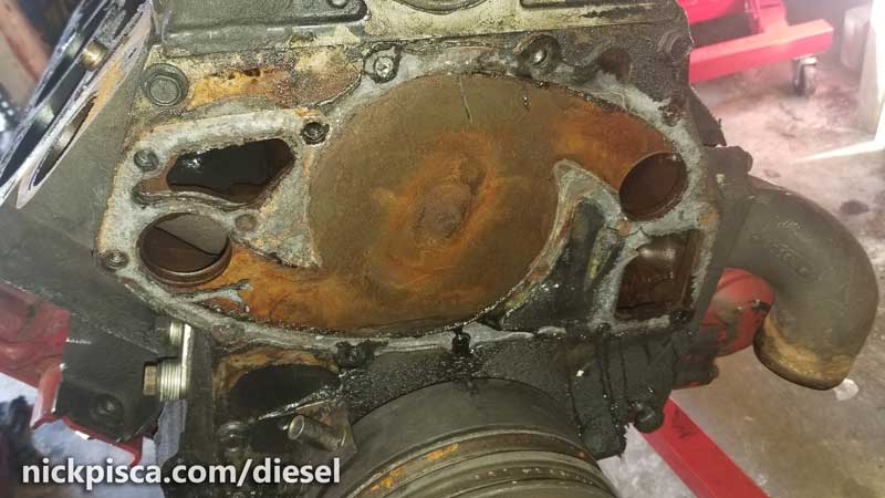
Next, I removed the gear housing.
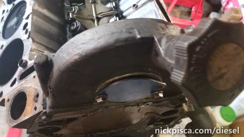
It’s held on by four bolts on the sides and back.
Top view:
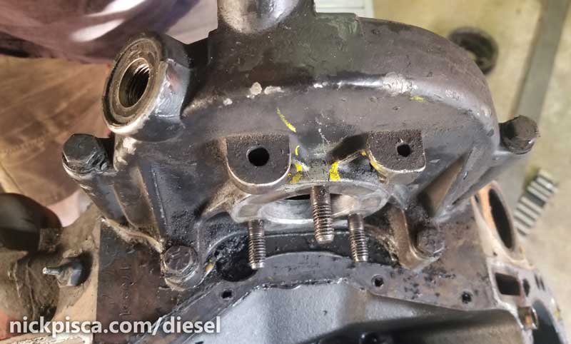
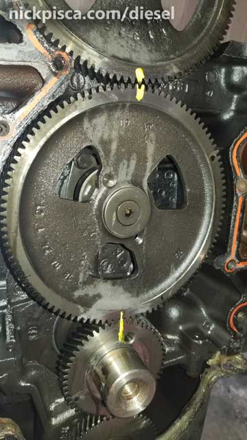
Before you get all giddy and rip off the IP gear housing, if you are careful, you can extract the cover without nudging the IP gear off a tooth. This is important because you can use a paint pen to mark the location of the gears for reassembly. Since I’m ripping this thing apart for the internal parts, that doesn’t matter to me, but most people are trying to retain the timing of their vehicle. This means knowing exactly the location of the timing position, especially if one is not trying to remove the front plate.
Using a finger in the center of the IP Gear, hold it down against the cam gear (behind the front plate). The IP timing gear has some pegs and flanges that make it easy to catch on the IP gear housing, so constant pressure is necessary. Then gently pull the housing off the gear.
Also, I removed the front plate and rear plates, detailed here:
When removing the front cover, be extra careful to not jostle the engine so that the IP gear doesn’t fall off. Not only will it ruin your timing marking, but it’s not light. It’d definitely break a toe if it fell.
With the front cover off, I marked my gears anyway. I know I’m not going to retime these parts, but I can’t resist the habit.
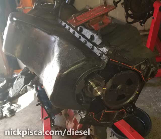
Then I flipped the engine on the stand. This really sucks with an IDI. Maybe next time I mount my engine, I’m going to lube up the mounting cylinder with grease or something because it’s totally not doable with the rotation bar they provide. I put a 6′ pipe on the end of the rotation bar, and that helped. With the heads on, it is even too difficult to rotate with a pry bar. I have to use my shop crane to rotate it by hooking on the motor mounts (hence the reason why the mounts are still on the block). By the time I tore this apart and put it back together, my rotation bar was “C” shaped from all the torquing.
Time to pull the oil pan bolts.
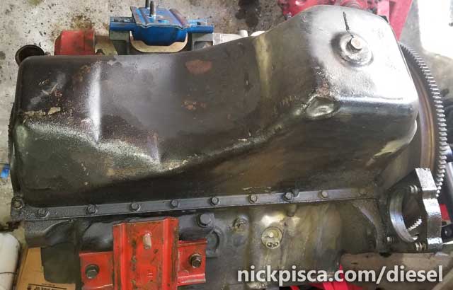
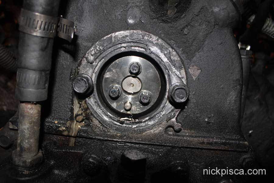
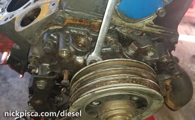
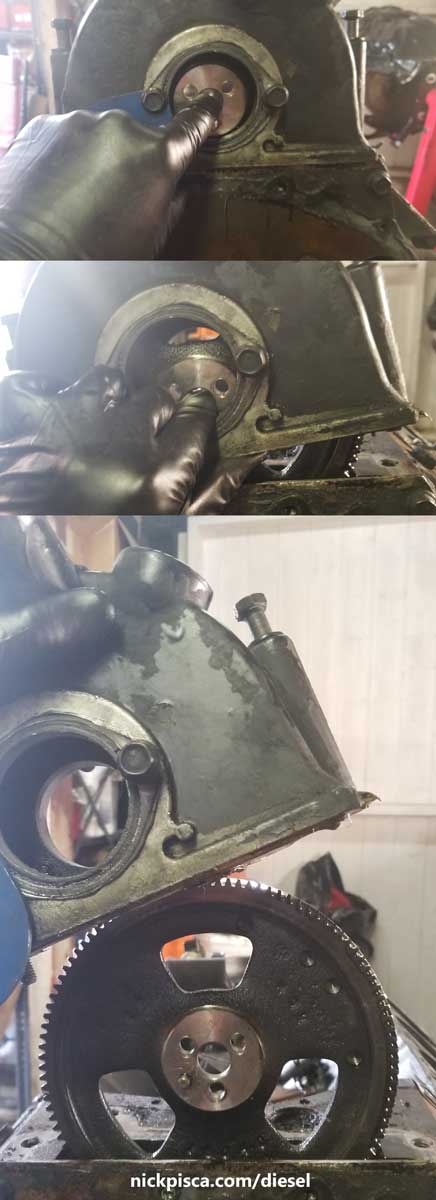
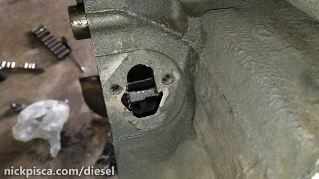
But first, I removed the C6 Flexplate/Flywheel.
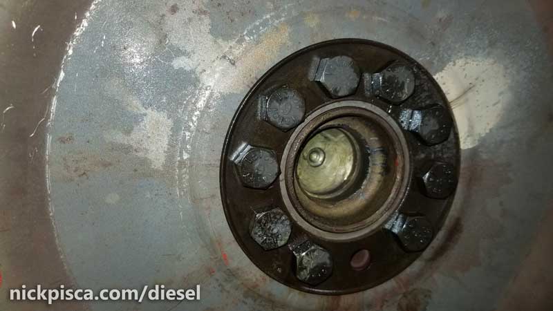
These bolts are spec’ed to have lock-tite on them, so they can be hard to extract. Using a long 3/8″ extension, I found a place to lock the flywheel while undoing the bolts. Without a means of stopping rotation, the crank will just spin and spin.
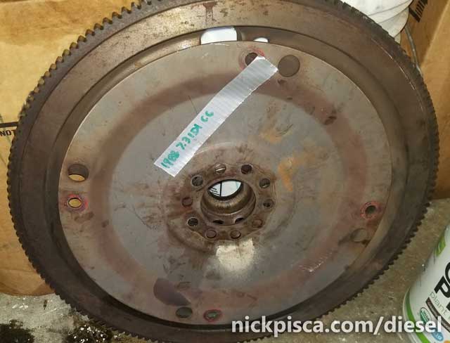
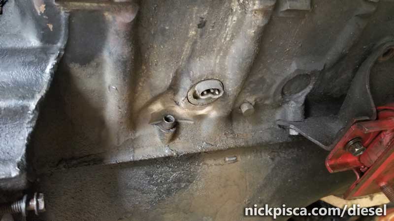
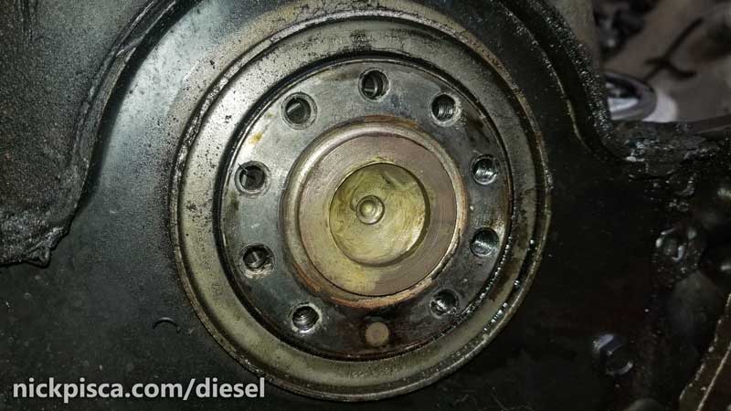
I set the flywheel aside (it’ll be used for the rebuild), and checked the condition of the rear crankshaft and rear main seal.
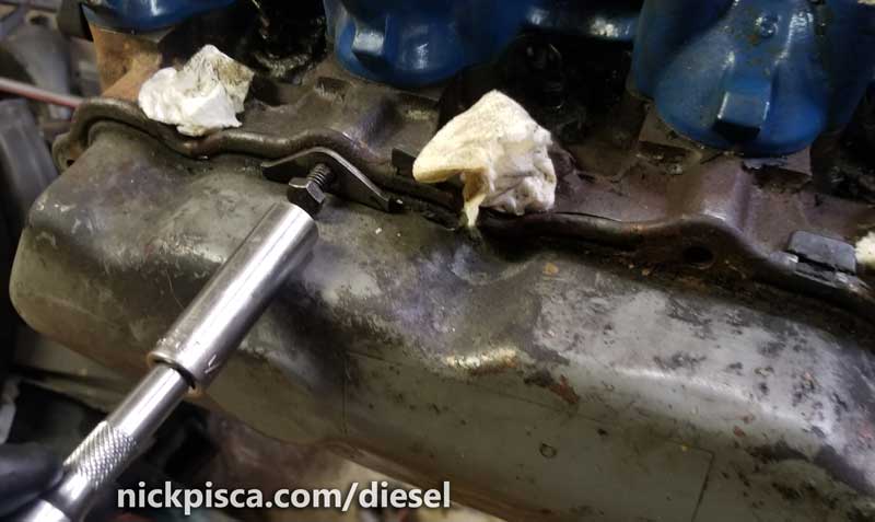
Prying off the oil pan is a pain if the old sealant is still strong. I had to use a paint scraper (careful not to scratch the mating surfaces) to separate the two.
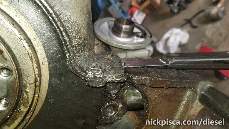
One thing to be careful with the scraper is, there are small metal studs at the corners of the oil pan. These will damage your scraper if you are not delicate. Also, it might damage the block if you pound on the studs. You can’t see the studs in the picture above because the darn things are covered in such gunk and grime.
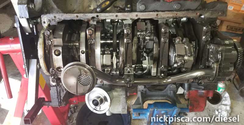
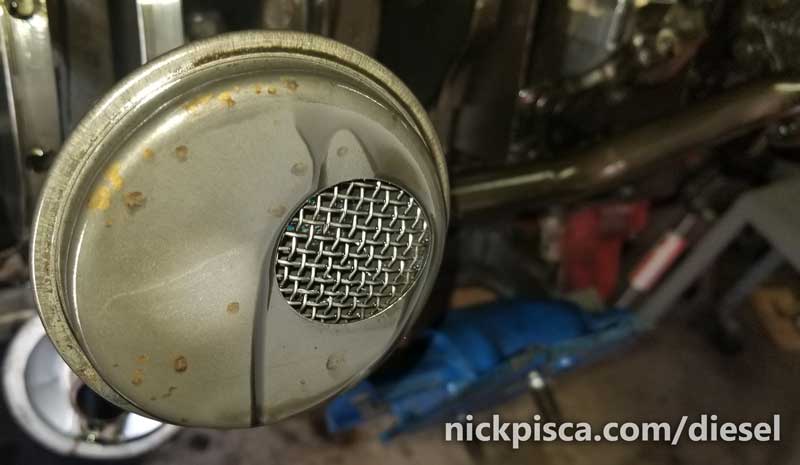
The oil pump and its pickup is located underneath the crankshaft. It’s held on by three bolts up front (by the pump) and one nut mounted on a crank main stud. Strainer in the pick up:
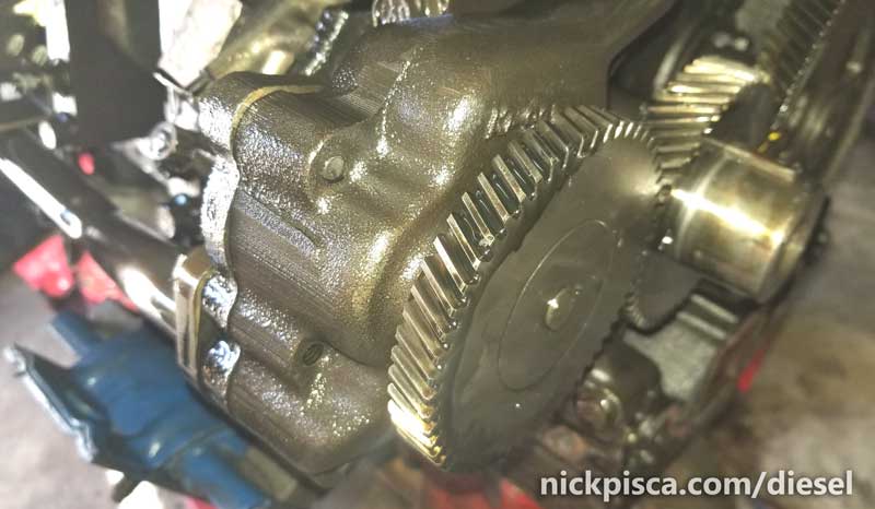
The gear on the oil pump doesn’t have a timing mark because its rotation is irrelevant. It can be removed without any markings.
Next I removed my fuel pump / block-off plate. (I went with the e-pump long ago, so whenever I encounter these old lift pumps, I usually just toss them in the trash.)
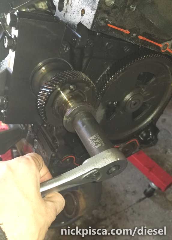
Time to check out the crank stuff.
If I need to turn the crank, I just put a large socket on the harmonic balancer retainer bolt. This will allow me to access the rod caps more easily.
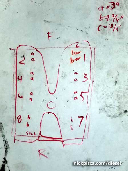
Now, if you don’t already know, marking down all my rod labels and their respective cylinders is crucial for reassembly. I’m going to use these rods, pins, and crank in a future project, so I want to reunite all these parts in their respective places at a later date. So some drawings are crucial to make sure everything is good, before I tear this all apart.
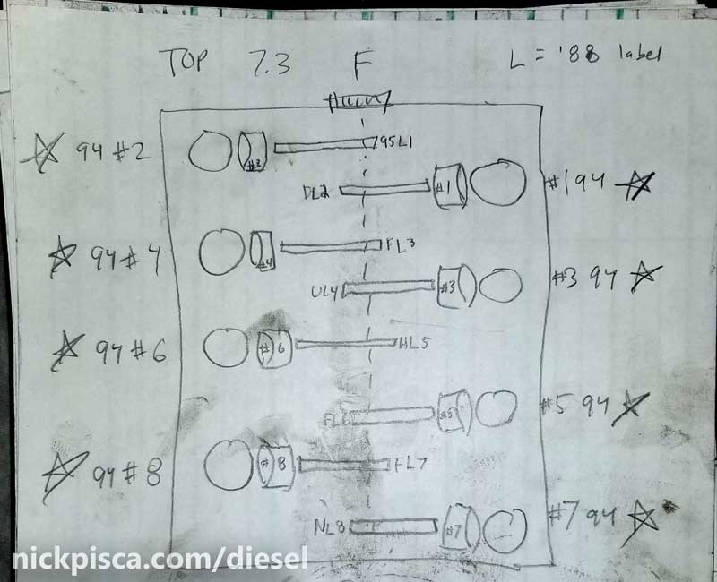
So I marked these letters and numbers down:
Sadly, not all rods were uniquely labeled, so I had to use a paint pen to add another marking for some.
The rod caps have two nuts each that a trivial to remove. Pull them off, and then carefully pry off the rod cap. They will be difficult to separate, so a small screwdriver can really help. Just as long as I don’t damage the mating surfaces.
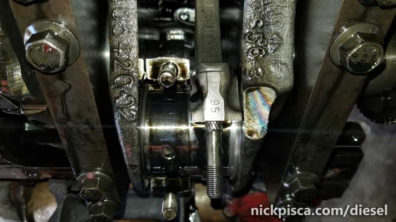
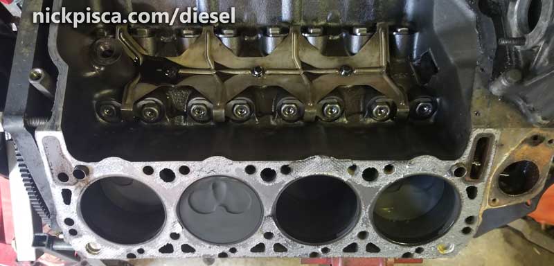
With the caps removed, those two rods (and their partner pistons) can be pushed through the block.
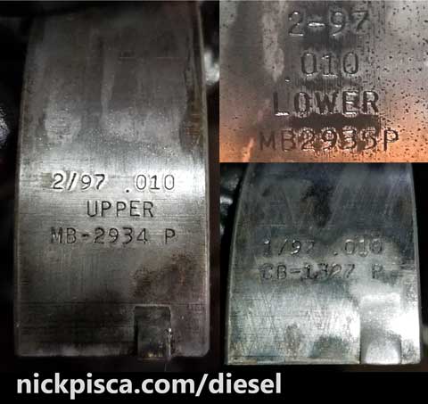
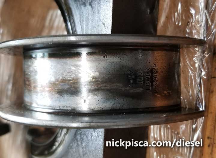
The rods have bearings that are essential to the performance of the engine, and these will be needed to size and order new bearings for the rebuild. Check on the back of these semi-cylindrical strips of metal to get the size (Standard, 0.010, 0.020, or 0.030) you might need to order.
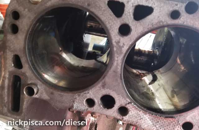
I don’t have a good picture of the piston extraction (just push them through the top of the block deck), but there is a lot more on this topic in this article:
7.3 IDI Piston Ring Gap Measurement, Custom Grinding, and Proper Installation
One by one, I pull the pistons and rods, and label each for their respective cylinder. I’m going to re-ring them in a new block, so the respective cylinder isn’t that crucial, but most of the time, these pistons will go back in the engine block and be reused in this same setup.
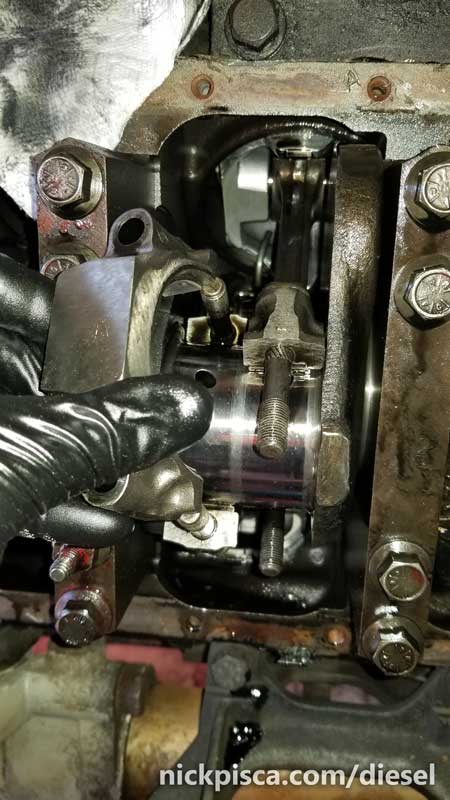
The crank is now ready to be pulled:
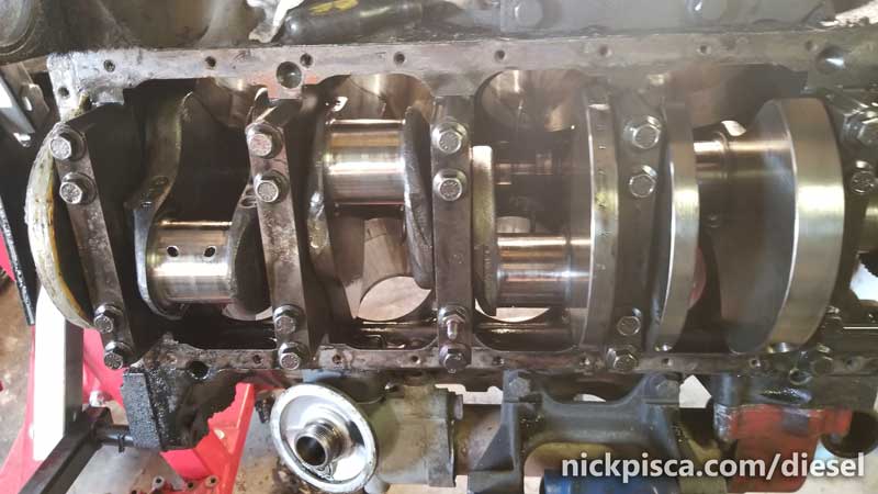
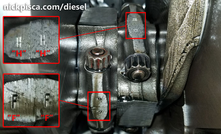
The crank mains (the rectangular thick metal retaining blocks, held in by four bolts each) are wedged into the block and need to be replaced in the exact spot they were designed for. Lucky for you, IH stamped markings and arrows on each to ensure proper reinstallation. It counts from 1 to 5, with 1 starting at the front of the block and 5 residing at the rear. The arrow points to the front.
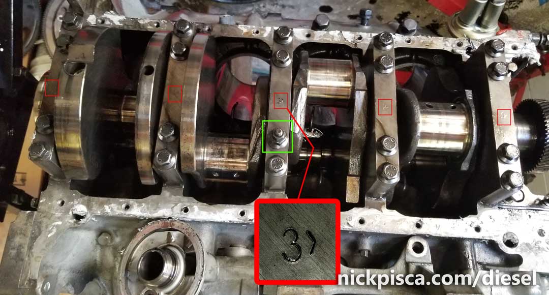
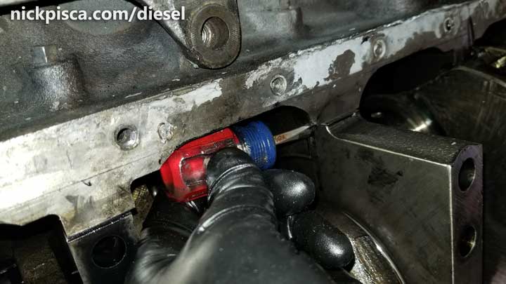
The mains came off pretty easy with a stumpy flathead screwdriver. It just fits in the space between the mains and there is a small notch that is used for prying. With the crank in place, it is hard to wiggle that metal out of the block, so prying with a screwdriver is your only option.
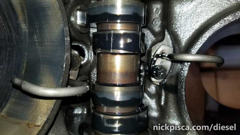
I pulled them off and took a look at the “BELOW” crank bearings. Some good, and some bad.
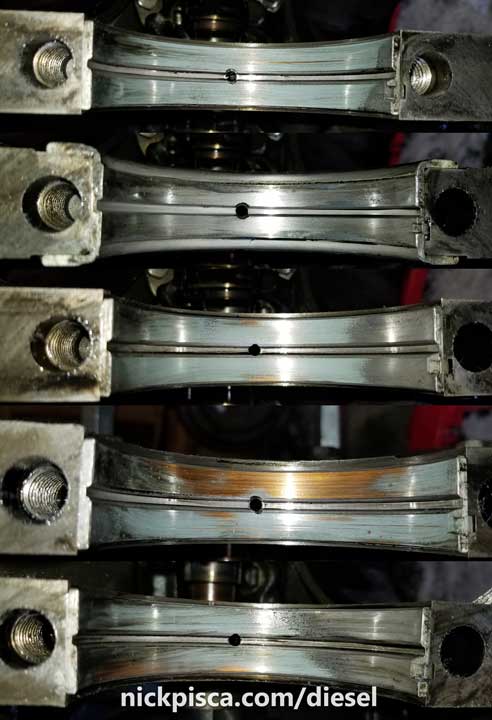
The middle bearing has side flanges to resist the forward and backward thrust from the resistance of the engine. These are called Thrust Bearings.
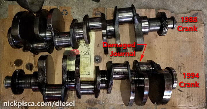
I pulled the crank and put it next to the other crank I have. My ’94 IDI had a damaged crank rod journal.
With the crank out, you can see the camshaft on the center of the engine.
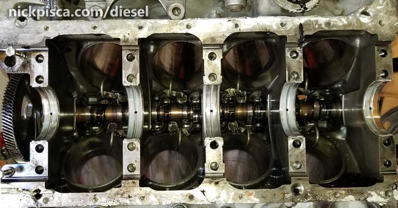
You can really get a good view of the oil squirters and and cam components from underneath.
I’m going to put off the cam extraction for a few weeks. I got too much other stuff to get done and I’m not going to use this cam at the moment anyway.
I pulled off the oil cooler because this cooler was purchases on one of our roadtrips, and I had to fork over a lot of money to the dealer for a new goddamned cooler. So I’m going to reuse this new oil cooler (only has about 13K on it) rather than trust the oil cooler on ’94 block. (I was right, because when I disassembled the ’94 coolers assy, the seals were super old and brittle, even though the PO claimed he did a full rebuild on that block. Pffff.)
Here’s the info on the Oil Cooler extraction and disassembly :
So far, this is where I’m at. The block is sitting in the corner of the garage with the cam in it. I took the cam rollers out and archived them, but like an idiot, I didn’t photograph them. They slide out the top of the block without any resistance, so it’s easy enough to extract.
The only thing left is to pull the camshaft. Then I can finally get rid of this ’88 IDI core. It’s a huge paperweight in my garage, and I need the space.
This post is in progress. More to follow about the cam components. Stay tuned.