If you have been following my progress with the latest rebuild, you know I left off at the point of measuring the gaps in the rod bearings. I got the crank mains measured and successfully installed the new crank in the ’94 block. Next I need to verify that all rod bearings are within spec as well.
For the uninstallation of the pistons and rods, check the aforementioned link for all that prep. Removal is pretty simple, just undo the cap nuts and pry off the rod caps. Then push the piston out of the top of the deck.
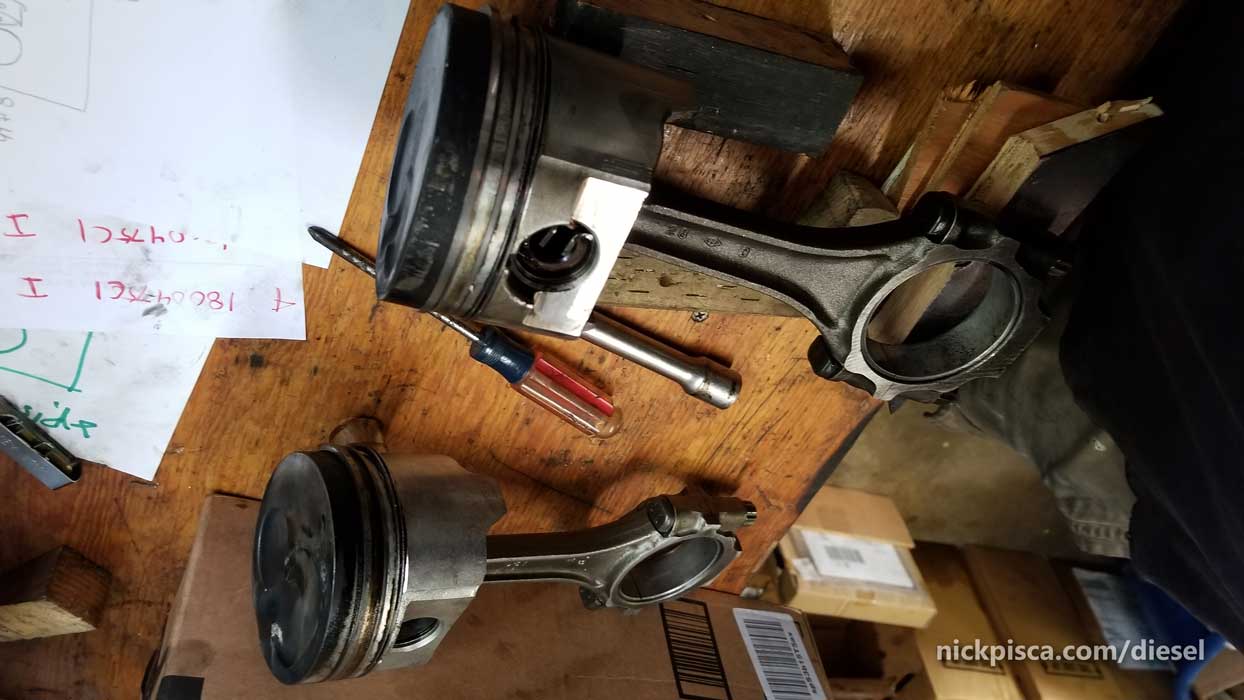
After pulling and labeling all the pistons, I laid them on the table to assess their condition. In order to pull off my plan, I need to move the ’88 crank into the ’94 IDI block. That means, to make things easy, I need to bring the ’88 connecting rods with me as well. Which means I need to transfer each respective piston from the ’94 cylinders with their ’88 connecting rod companion. Since neither of these engines were rated for the turbo, that means the pins are interchangeable. (On the turbo version, the pins are slightly larger diameter. The NA version has 1.110″ diameter pins, while the Turbo has 1.308″ pins. NOTE: If you try to swap to the turbo setup, you need to find the companion turbo-rated pistons as well. I’m planning on writing an IDI piston ring write up once I collect all my photos.)
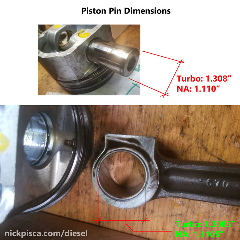
Lucky for me, I measured my pins with my schnazzy new calipers and they were both within three ten-thousands of each other. That is effectively an identical diameter, so either the ’94 or the ’88 pins would be usable. I elected to go with the ’94 pins, just because I’m going with the ’94 pistons, so I know they nested in the piston already.
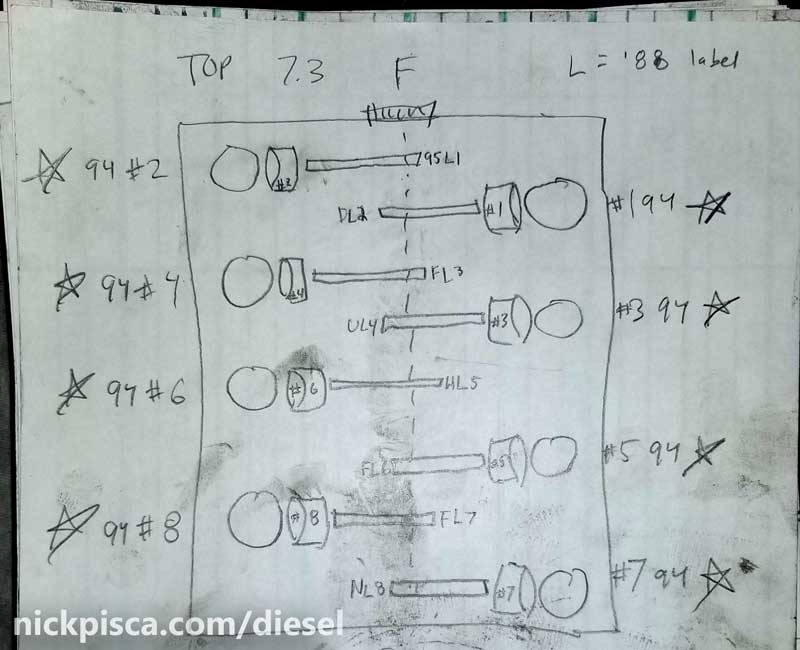
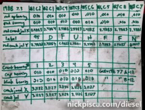
I drew up a chart to make sure that I mate the proper connecting rod with their respective piston. This way, I make sure that my pistons go exactly with the right cylinder, and the connecting rod goes exactly back with the respective position on the crank. (However, this is kind of unnecessary, because I measured the bores and journals, and I am replacing the rings, and custom sizing them per each cylinder, and I’m replacing the rod bearings, but regardless, it’s good practice to label and identify every part in the engine. But in the beginning of this rebuild, my original plan was to reuse the existing piston rings, but after a gap inspection, that was scrapped for a plan to custom gap oversized rings. Article to be written.)
Pressing out the pins.
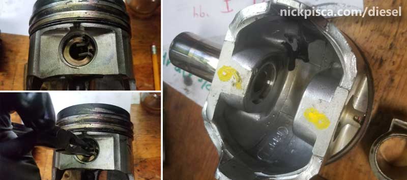
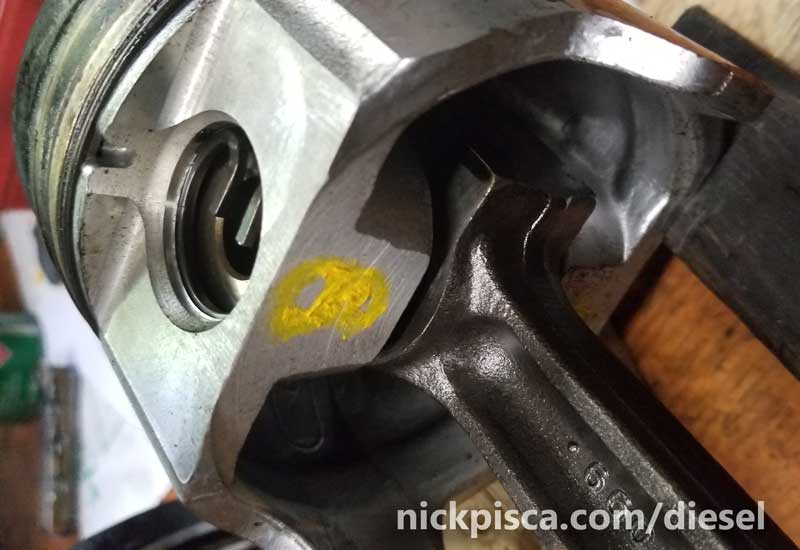
I laid out the pistons and their respective partners from the opposite engine. My drawing above explained which rods went with which piston. The process is pretty easy: using a needle nose pliers, I pulled out the pin retainers and pushed out the piston pin through one side. Then I carefully made sure the pistons were oriented the exact same way (using the rod letters and the piston pre-cup depressions as guides), and swapped the rods. Using a lint-free towel, I cleaned the pins and journals, and then applied some clean new engine oil to the surfaces to make sure they are properly lubed.
Installing and Measuring the Rod Bearings.
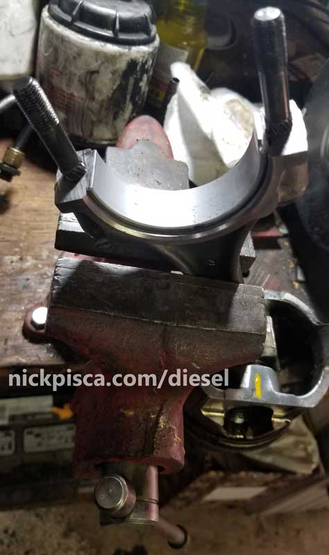
With the pistons and rods properly swapped, I archived the ’88 pistons and ’94 rods, and took the good rods and pistons to the vice. Careful not to damage the piston, I mounted the rods in the vice to have the bearings sized.
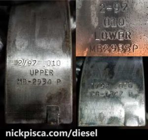 When doing a bearing project, you will need to order new bearings. Bearings come in various sizes, based on the machining of the crankshaft journals. The only way to get a ballpark figure on ordering a new set, is to flip over the bearings in the rod and cap, and read the text on the back. Typically, they come in “Standard,” “0.010,” “0.020,” and “0.030” oversized. As the crank journals are ground down in machining, they are sized in increments of ten thousandths (one hundredths). The purpose of the bearing is to make up this difference. Unlike the crank bearings, the rod bearings do not have an “UPPER” or “LOWER” designation.
I ordered a set of 0.010 oversized bearings for my rods a while ago, and I’m now ready to install them. The old bearings slide out pretty easily. I cleaned up the rods and caps, removing any oil or grime that might have coated the mating surfaces. Then, WITHOUT APPLYING ASSEMBLY LUBE OR OIL, I installed the replacement bearings in the rod and cap. Dry. Also, there is a notch and key in the bearing that needs to line up.
Then I put the cap on, and torqued the rod cap nuts down to the proper spec: 38 ft-lbs on the first torque, then 51 ft-lbs on the final pass.
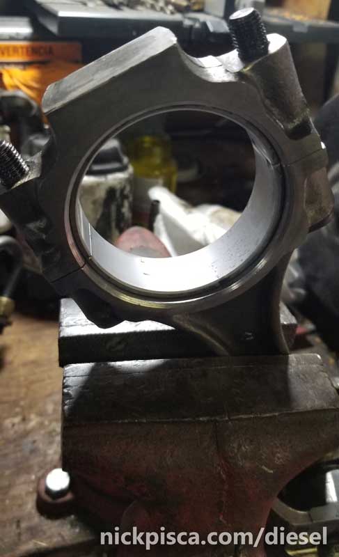
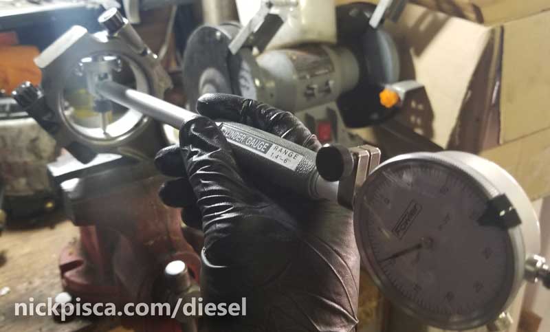
 With the cap properly torqued on, it now is compressed into the size for operation. Using a bore gauge and micrometer, I needed to make sure that the bore conformed to the proper dimensions. I had already measured the crankshaft journals when I did the crank bearings (explained in the other article), and wrote down the dimensions accordingly. All of the rod journals measured between 2.4882″ – 2.4885″ in the X and Y direction (of course the x and y are arbitrary because the rod rotates, but you get the point).
From the Ford Service manual:
Connecting Rod Journal Diameter
- Standard Size: 2.498″-2.499″
- 0.010 Undersize: 2.488″-2.489″
- 0.020 Undersize: 2.478″-2.479″
- 0.030 Undersize: 2.468″-2.469″
If your journal size is worn in between these increments, a machine shop will be needed to grind the journals to the next smaller undersize dimension. Then, the bearings will need to make up that hundredth of an inch.
Knowing the ’88 crankshaft standard journal size is approx 2.4882 inches, I set my bore gauge to that value. Considering that this is about 1-3 ten thousandths of an inch deviation from the other journals, then it’s a good base point to begin from. Then, the spec says the Main Bearing gap needs to 0.0018′-0.0046″ and the Rod Bearing gap needs to be 0.0011″-0.0036″. Too small, and the oil will not flow in between the bearing and journal. Too big, and the lack of resistance will let the oil lose pressure, so the 11 to 36 ten-thousandths is crucial to a successful engine rebuild.
One by one, I clamped the rod into the vice, cleaned the surfaces, installed the bearings, torqued them to spec, and measured the bore. All were within 1.25-2.75 thousands of an inch, which is well within spec.
 Installing the Pistons, Rods, and Caps into the Cylinder:
Once they were all verified, then I disassembled everything (again) so that I could put them on the crank. Before I could do that, I had to do the Piston Ring work. I’m not going to detail that in this article. Here is a more detailed process of how I dealt with the piston rings, but to quickly summarize, it involves custom grinding oversized rings down to just under the Ford spec (long story), and using a piston ring compressor tool, a mallet, and some rod bolt covers to pound the piston-rod assembly into the cylinder.
Before I put the assembly in the block, I coated the newly installed rod bearings with assembly lube or engine oil, because it’s a lot harder to reach around the crankshaft to properly lubricate the mating surfaces.
For more info on my piston ring saga, visit this:
7.3 IDI Piston Ring Gap Measurement, Custom Grinding, and Proper Installation
Finishing up.
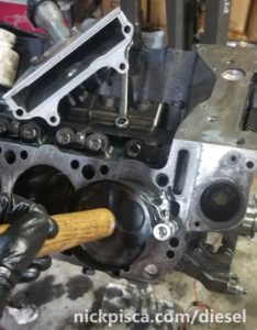
With the pistons reinstalled in the block, I carefully positioned the rod bolts around the crank journal. Scratching the journals on the crank is not an option, so a pair of rubber vacuum hose around the threads is added insurance. Also, having a partner help out makes this job a lot easier, but I had to do it on my own.
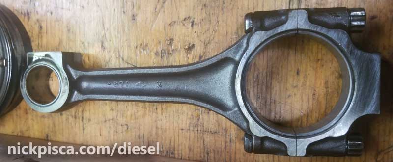
When capping the rods, makes sure the piston is oriented properly (the precups should be on the top-most side of the cylinder) and the rods identification numbers match together.
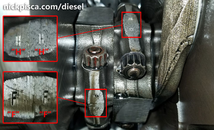
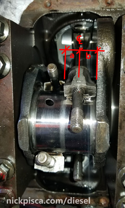
I’m 99% sure that if you don’t match the rod ID letters, the rod won’t fit together right (they are oblonged), but just make sure they are correct. Also, I made sure that the eccentric part of the rod is orientated like the image below, where the thicker side (measurement “b”) is closer to the crankshaft wall and the thinner side (measurement “a”) is towards the middle:
Once all the rods and pistons are installed and aligned properly, I coated the cap bearings with engine oil and then capped the rods. Also, as stated above, make sure the piston is oriented the correct way before torquing the rod nuts and caps down. I torqued the nuts to 38 and 51 ft-lbs in that sequence. As I worked my way down the shaft, I rotated the crank to give me optimal torquing access. Also, by turning the crank, I can make sure I didn’t mess up my micrometer and bore dimensions, and it hasn’t seized the rotation. A lot of guys will use Plastigage to verify that the gap specs were correct. But with my bore gauge and micrometer going down to ten thousandths of an inch, I’m confident it was fine.
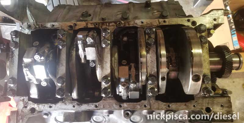
With the pistons, rods, and crank reinstalled on my project, I was then able to move on to the reinstallation of the front and rear IDI engine plates, the front and back main seals, push on the harmonic balancer, put on the heads and studs, slam on the Oil Cooler, and more. I even got it fired up in this video:
No warranty. You are responsible for your vehicle. For novelty use only. Not responsible for anything or anyone. Not responsible for damage to your vehicle, you, or anyone or anything.
Copyright 2000-2018 Nick Pisca 0001D LLC