Even though my original plan for this 7.3 IDI rebuild was quick and dirty, I eventually decided to invest some time, money, and effort into a decent piston ring job.
Background:
If you want to skip to the actual piston ring gapping and grinding, overlook this background section.
So I got this ’94 7.3 from a guy in The Valley. He claims the engine was recently rebuilt, but I don’t know. The engine had some decent wear, and aside from some sloppy gasket maker and the broken crank bearing, it seemed ok.
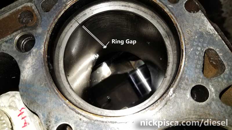
After I extracted the ’94 7.3’s pistons and rods, I inspected the existing piston rings:
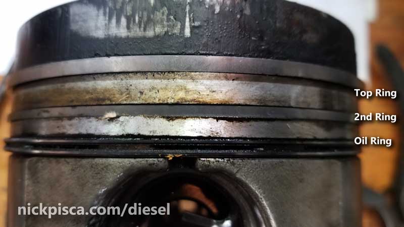
At first glance, they did appear to have very little wear and tear. Compared to my ’88’s rings (not pictured), these ’94’s looked pretty nice. So I thought I could keep these through the rebuild process.
However, just to make sure they are within spec, I measured all the ring gaps in their respective cylinders.
Measuring the Ring Gap.
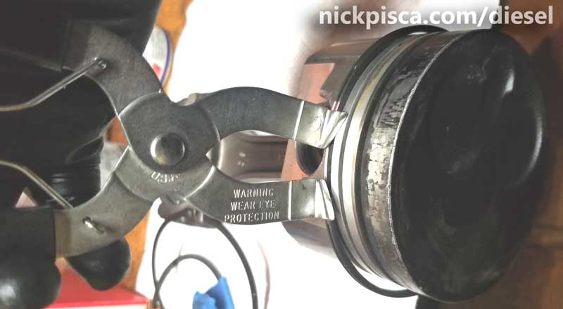
Using a Piston Ring Pliers, I removed the existing rings from the piston grooves. I’m trying to be careful, because I’m still operating under the assumption that I’ll reuse the existing rings.
I slid each ring one at a time into their respective cylinders and, using an empty cylinder, I pressed down my rings so that they sit further down in the bore.
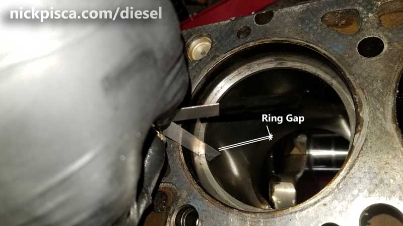
Once the piston ring is situated parallel to the deck and deep into the bore, then a proper ring gap measurement can be obtained.
In order to accomplish this measurement, “feeler gauges” need to utilized. If you don’t know what this tool is, it’s basically a bunch of thin strips of metal that have their thickness printed on the side. They go down to a few thousandths of an inch, up to approx 0.045″. The user just needs to use trial and error to figure out the best fit in the ring gap.
A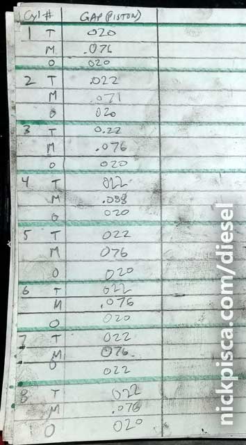 fter I measured all top-, 2nd-, and oil-ring gaps, I put them in a chart (see image to the right). Just for some comparison, here are the Official Ford Specs on the ring gaps:
Ring Gap in Bore (Engine Number 598753 and lower):
- Top: 0.013″-0.045″
- 2nd: 0.060″-0.085″
- Oil: 0.008-0.030″
Ring Gap in Bore (Engine Number 598753 and above):
- Top: 0.013″-0.023″
- 2nd: 0.062″-0.072″
- Oil: 0.010-0.020″
My engine serial number is greater than 598753, so I’m using the tighter spec. Almost all of the gaps were at or above the standard Ford spec.
On many of the IDI forums, there are examples of guys running VERY TIGHT gaps on their engines. Also, infamous IDI guru R&D IDI Performance has a set of rings in their inventory that calls for tight gaps as well. They mention:
- If installing in a worn bore, extra care need’s to be taken to file the gaps properly. Ring gap need’s to be filed to between .014″ and .020″ on the 6.9, and .018″ to .024″ on the 7.3. On an engine with wear, the rings need to be gapped to the tightest part of the bore.
Considering I have the engine all apart, I figure I’ll just buy new rings.
Determining the Type of Piston Ring Size
Since the cylinders can be machined to various overbore sizes (usually in increments of 10 thousandths), the piston needs to be measured at the skirt to ensure proper cylinder ring size. How to measure the skirt? Measure the largest diameter with a micrometer at 1.23″ down from the edge of the oil ring groove, like in the image below:
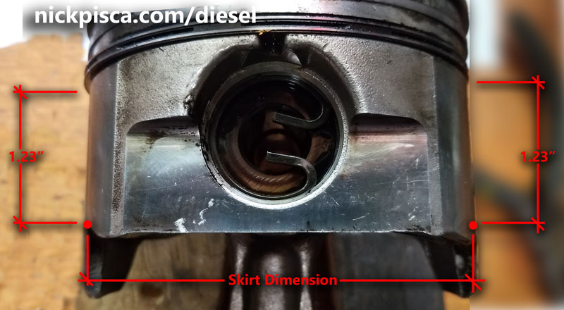
I had to borrow a micrometer from EMS in Inglewood, because my set only went up to 4″. If you are working on a 6.9 IDI, then a 4″ micrometer would be sufficient, but the 7.3 bore exceeds 4.10″. My piston skirt measurements are to the right:
 Using the Ford Spec:
Production Piston:
- Class U: 4.10325″ +/- 0.00025″
- Class B: 4.10375″ +/- 0.00025″
- Class A: 4.10425″ +/- 0.00025″
- Class C: 4.10475″ +/- 0.00025″
- Class D: 4.10525″ +/- 0.00025″
Service Piston:
- Standard Size: 4.10425″ +/- 0.00025″
- .010″ Oversize: 4.11425″ +/- 0.00050″
- .020″ Oversize: 4.12425″ +/- 0.00050″
- .030″ Oversize: 4.13425″ +/- 0.00050″
I was in a rush (borrowing the micrometer from a shop in their bay), so I didn’t have time to carefully check the tens-thousandths, however, I’m fairly confident my pistons fell into the “Standard Size” category. Knowing this, I was able to order a new set of “Standard Size” piston rings. They arrived, and I rechecked the gaps. Sadly, they all were pretty much exactly the same as the existing set of rings. So the PO was right; he did replace the rings during his rebuild, but they fell at the upper part of the spec. I’m trying to make this thing as compression friendly as much as possible, so I wasn’t going to settle for out-of-bounds specs.
I returned the Standard Set and ordered a set of oversized rings (same hyperlink as above). I like the Clevite rings the best (just a personal preference), but unfortunately, I wasn’t able to order a ten-over or twenty-over. The only set I could obtain was a 30-oversized. This would mean more grinding, but considering we are talking about tenths and hundredths of inches, it shouldn’t be too much of a job. Wrong. Doing 8 cylinders with 3 rings each meticulously takes some time.
Grinding Piston Rings for a 7.3 IDI:
For a decent primer on how to custom grind your rings, visit this guy’s youtube: (Note, his tutorial is not for an IDI engine, but the general information is decent to know.)
His presentation is pretty solid. I didn’t have one of his fancy grinders, so I just used a hand-held electrical grinder in a vice. It’s a little dicey, because the slightest mishap could grind off WAY TOO much material. But I was really freaking careful, and managed to set all my rings to the following gaps:
- Top: 0.013″-0.014″
- 2nd: 0.045″-0.050″
- Oil*: 0.010″-0.011″ (* read more in “Oil Ring Composition”)
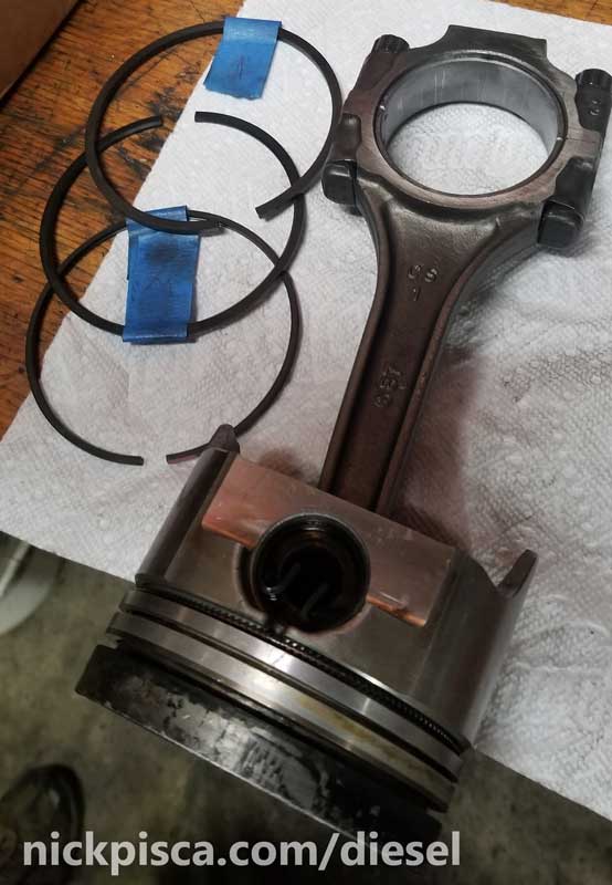
I ground the 2nd ring gaps just UNDER the spec, making a set of rings (Top, 2nd, and Oil) for EACH cylinder. Once they were properly ground and gapped, I labeled each with a small piece of blue painter’s tape (it doesn’t leave residue on the ring) to identify in which cylinder this particular set will reside. Each cylinder is slightly different, so assuming each grinding will be universal isn’t possible, unless you had each cylinder sleeved and professionally honed.
I chose not to go as far as the 20 thousandths that R&D and other guys were running, but I did go a little under spec to cut down on the blowby. (Note, using a standard electric grinder is not really recommended when you are trying to shave off a few thousandths of an inch. However, if you are the type to be extremely careful, it’s not that difficult. Also, using a grinder makes it hard to ensure the ends will have a perfect 90deg, but it’s doable.)
Oil Ring Composition:
The oil rings are comprised of 3 components: the center wire, the coil, and the outer retention ring. The outer ring has an internal groove that lets the coil rest in it when compressed in the chamber.
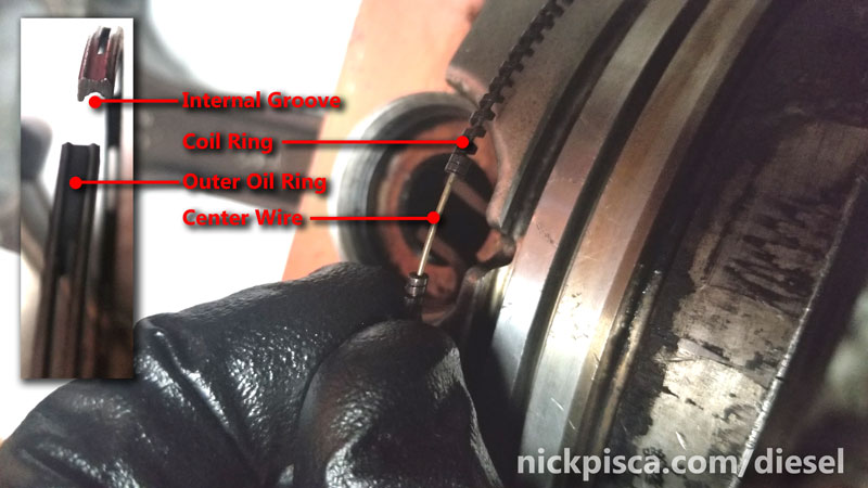
Unlike the Top- and 2nd-rings, the Oil ring only needs the Outer Oil Ring sized. The coil will compress (as most springs naturally do) in the groove when it is conformed to the cylinder. Also, the ends of the coil have a tighter frequency which don’t lend themselves to grinding even if you wanted to do it. The center wire also doesn’t need grinding or clipping, because the thing doesn’t reach around the entire circumference of the piston anyway. Basically, the oil coil and oil center wire are good to install without any gapping or grinding required. They are flexible enough to work in any bore of a typical 7.3.
Setting the Rings in the Piston Grooves:
With each piston wiped down and each ring groove cleaned out (Seafoam really helps break up the carbon), I set all the piston assy’s with their companion new ring set (see image below). Cleaning the grooves is imperative, because it ensures the rings will have enough room to set. Also, it will let you get an accurate “Fit in Groove (Side Clearance)” measurement to conform to the spec.
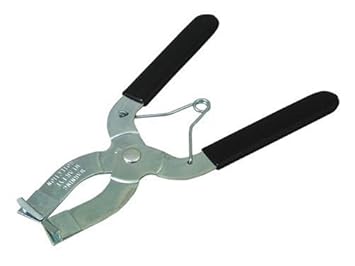 First, I wrapped the oil ring coil and center wire into their groove. This is pretty trivial and doesn’t require any special tools. Next, I used the Piston Ring Pliers (see image below) to expand the ring just big enough to encompass the coil and wire, and it rested in the oil piston groove. There are some whippersnappers on the net that think they can put a piston ring in the groove without pliers and I say that’s a good way to damage your piston and rings. The pliers is something like $7, so there is no excuse to invest in the proper way to work with rings.
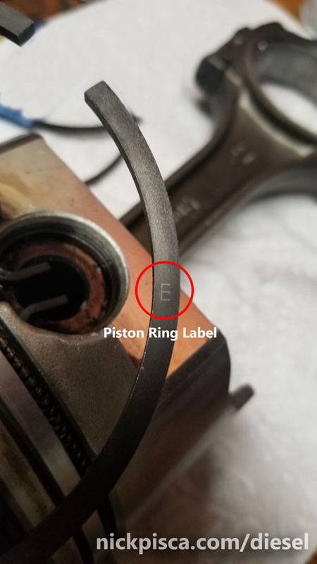
I did the same for the 2nd and Top Piston Rings as well. With the 2nd and Top rings, there is a stamped letter or dot indicating the “top” of the ring, so that it orients the proper direction in the chamber.
And
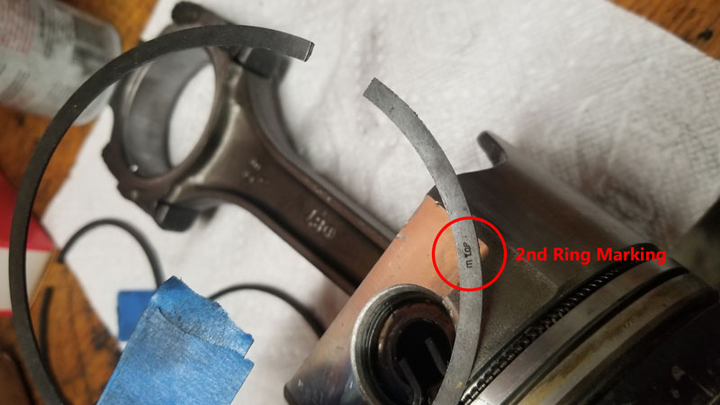
The oil retainer ring doesn’t have a top or bottom, because it will work fine either direction.
With the rings installed on the piston, they will dangle out of the groove like an old man’s testicles. This is normal. Their natural radius is to rest a little bigger than the chamber. Once they are compressed in the chamber, they will rest up against the sleeve walls and make a nice fit once the engine is up to temp.
The last step is to verify the “Side Clearance” with a feeler gauge. This is the gap between the groove and the ring. I don’t have a picture of this, unfortunately. The spec is:
Fit in Groove: (Side Clearance) Engine Number 598753 and below:
- Top: 0.002″-0.004″
- 2nd: 0.002″-0.004″
- Oil: 0.001″-0.003″
Fit in Groove: (Side Clearance) Engine Number 598754 and above:
- Top: 0.002″-0.004″
- 2nd: 0.003″-0.005″
- Oil: 0.001″-0.003″
All my rings conformed to the Side Clearance spec, so they are good to go for reinstallation in the block. There is some great information on the rod bearing and piston pin maintenance and replacement here, if you haven’t already read it: (This is good to know prior to reinstalling the piston assemblies before moving on with this article on the pistons and rings.)
 Reinstalling the Pistons back in the Block:
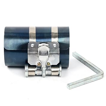
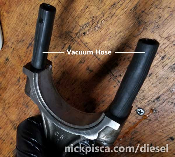
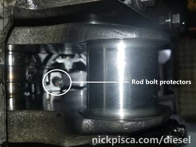
Before anything can be done, some special tools are needed to get the pistons back in the block. First thing is, a piston compressor is absolutely necessary. There is no way you are getting these VERY TIGHT and strong IDI piston rings inside the chamber without serious help from this tool. Also, it helps to have some 2-3″ sections of vacuum hose to wrap the rod bolts. This prevents the rod threads from scratching the crankshaft journals when they are installed. Some guys use fuel hose for this, but I don’t like fuel hose. It’s too rigid and too thick. Vac hose is better because it is a bit thinner and more rubbery, so it allows the “forking” of the crank journal with minimal resistance.
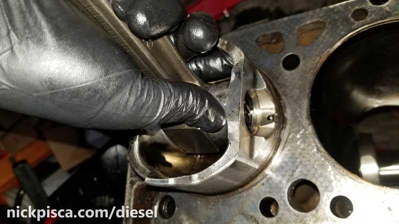
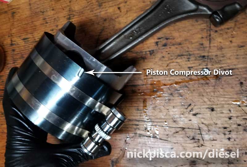
The Piston Ring Compressor makes the whole process VERY easy. Just lube up the tool with engine oil, wrap the cylinder with the divots pointed down (see image below), and tighten with the square elbow wrench provided. The reason why the divots need to point “down” (or in other words, pointed toward the interior of the engine block), is because this allows the compressor to act kind of like a very very very shallow funnel. The divot side is slightly smaller radius at the end, so it lets the tool mate with the deck of the block, but also compress the rings to their smallest configuration, thus allowing it to transition to the chamber relatively easy. There are other compressors you can buy, but I like this because it’s fully adjustable for other bore sizes. Also, it’s under $10, so there is no reason not to have it.
With the rings fully compressed in the tool, I pointed vacuum hose protected ends into the cylinder, applied a liberal coat of engine oil to the rod bearing, and slid the piston skirt into the chamber, up until the tool stopped it. Then using a wooden (NOT METAL) mallet or handle, I tapped it into the cylinder. The key is firm and decent hits to the top of the piston, so that it has enough force to “hop” the tool to the chamber, but not so much force that it could cause potential damage to the block or rings.

With a few decent whacks, the piston will fall into the cylinder without any issues. If it does get hung up on one ring, do not keep pounding away. Instead, I would remove the piston (even if 2 of the 3 rings seated ok), reapply the compression tool, and try the reinstallation all over again for that cylinder. I had to do that once, and I’m relatively familiar with it, so even a veteran can get somewhat unlucky every once in a while.
 As seen in the picture above, the piston precup depressions should be on top of the piston when situated in the block, and as stated in the Rod Bearing article, the rods need to be oriented with the fat side of the rod pointed closer to the main bearings. See that article and this image to the right for more info.
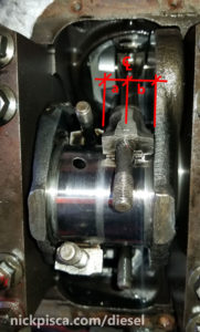
When sliding the pistons down to mate with the crank journal, be sure to use the vacuum hoses to guide the way.
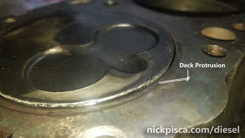
While turning the engine, I noticed piston protrudes above the block deck surface at the top of the stroke cycle. At first, I thought maybe my rods were the wrong size (there are differences in the rods and pins, as stated in the article below), but then I confirmed from other IDI experts that deck protrusion is ok, as long as it falls within the allowable specifications: 0.010″-0.036″ Using a straight edge and feeler gauge, I measured my deck piston height to be 0.017″, so I’m good.
That pretty much sums up the piston, piston ring, and gapping procedures. The rest of the piston-rod assembly work is concluded on the Rod Bearing article, which can be found here:
No warranty. You are responsible for your vehicle. For novelty use only. Not responsible for anything or anyone. Not responsible for damage to your vehicle, you, or anyone or anything.
Copyright 2000-2018 Nick Pisca 0001D LLC