What started with a cracked block and friend on FTE selling me a spare ’94 U-haul van 7.3 block, ended with a pretty fun engine rebuild project for my ’88 IDI van.
The Backstory:
The guy from FTE posted about how we was trying to unload his recently-rebuilt E4OD and shell on the forum. I PM’ed him about obtaining the block, because I had been fighting oil-in-coolant leakage in my original ’88 7.3 engine, which I had sitting around on an engine stand after my 7.3-to-6.9 spare engine swap. After checking everything on that ’88 7.3 for oil leakage (even swapping the heads in the engine bay), I concluded that somewhere in the oil galleys or block, there is a pinhole leak or crack. I was fed up. It was a lot of work to do all those repairs just to have it continue to leak oil in the coolant. And emulsifying and cleaning the coolant system was expensive and tedious. I was ready for a new block and ready for a rebuild.
Originally, the spare 6.9 was going to be the candidate for the garage rebuild. I got that engine from an ’84 IDI E350 on a whim, and it even came with the rare Banks van turbo kit. After parting everything out of that van, I pulled the engine (by myself) and stowed it away in the garage. Coincidentally only a few weeks later, the oil-in-coolant crisis emerged in my ’88 7.3, and it derailed my 6.9 IDI rebuild project.
The guy from FTE lived up in the Valley, only a few dozen miles from house. I drove my van up there to negotiate some parts from that U-haul. The owner had taken his U-haul to a shop in Van Nuys because it was squeaking odd, and they had disassembled the IDI. They had the block ripped down to the deck, and by turning the flywheel, you could see the 7th cylinder was lagging. Likely, the bearings had failed. I didn’t know. I had to gamble that whatever was wrong, I could use that block to replace my cracked one. We worked out a deal that I could take any engine-related part and the block for $400. In addition to the block and everything below the deck, I ended up getting the IP, GP’s, injector lines, injectors, heads, intake, EM’s, vac pump, alternator, steering pump, starter, cables, radiator, a few other valuable components. Not a bad plunder for only $400.
I worked fast. The shop helped me load the block into the back of my van, but the rest, I had to tear it all down myself. Within an hour, I had all the parts I wanted and headed back to Inglewood. It was like Christmas.

Once I got home, I had to deal with some family business which delayed my project. Not a big deal, since I had the 6.9 running ok. It had reduced power, high EGT’s, and some smoke issues from bad compression, but it drove, so I had time. I wanted this rebuild to occur over the next 6 months in my spare time. By July 2018, it would be used to go to the Canadian town of Tuktoyaktuk, on the Arctic Ocean, so I wanted it to be carefully assembled.
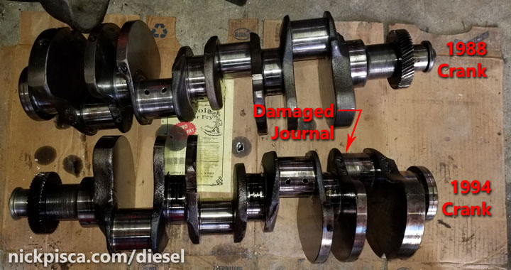
Eventually, I mounted the ’94 7.3 on a second spare engine stand and pulled the oil pan off. Within seconds, I found the issue. The rod bearing and connecting rod had totally disintegrated. It was a bad deal.
Not only did the connecting rod and its bearing have severe damage, but the crankshaft journal was substantially disfigured. One of the FTE members said that crank was toast.
I detailed the “crisis” in this separate article:
The Plan:
Upon my inspection, I didn’t see any major issues with the block, but rather, it was limited to the crank, connecting rod, and neighboring bearings. My plan was simple: Combine the best parts of both engines, and replace the bearings, rings, gaskets, and other significant parts. This would be the most economical way to do a quality rebuild.
Parts to use from the ’94 7.3:
- Block
- Pistons
- Pins
- Crank Mains
Parts to use from the ’88 7.3:
- Crankshaft
- Connecting Rods
- Oil Pump
- Oil Cooler and Headers
- EM’s
- Recently-new Heads
- Intake
- Oil Pan
- C6 Flexplate
New Parts
- Piston Rings
- Crank and Rod Bearings
- Harmonic Balancer (Dampener)
- GP’s
- Front and Rear Seals
Teardown
I ordered some parts and began the tear down. Paradoxically, I wasn’t just tearing down one 7.3, but two simultaneously. It was a confusing series of days, because I had to carefully label every part to make sure I don’t mix up the ’94 versus the ’88 parts. While the parts are technically the same, the variances in their bore, machining, and other tolerances required me to segregate all pertinent parts. This article details the 7.3 Teardown job:
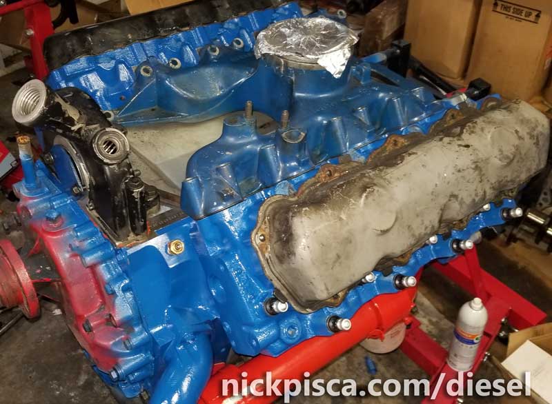
Eventually after days of pulling pistons and rods, bearings and mains, heads and manifolds, I completed the teardown and had two empty 7.3 IDI blocks sitting in my garage. I cleaned up the block to remove as much of the external gunk and grime so I had a somewhat clean canvas with which to start. It was time to begin the rebuild process.
The first part of the process was inspecting the block for any obvious signs of issues. The OP had done a sloppy job of gasketing the ’94 IDI and it made wonder if there were any mating surface blemishes or potential problems. Nothing out of the ordinary appeared. Also, I did my best to inspect the block for outstanding cracks or holes. This is hard to conduct without magnaflux, but I did the best I could with what I had. Next, I had the crank inspected by a machine shop to verify it was balanced. Since it was functioning fine in my ’88 up until the oil-in-coolant crisis forced it to sit the bench, I figured the crank was already within balancing specs, but it didn’t hurt to get a second opinion. I checked out the camshaft and its appurtenances, along with oil circulatory system. The bearing had shattered, leaving shards of bearing throughout the oil pan. Thankfully, the shards only affected the ’94 oil pump, leaving the rest of the system relatively untouched up to the filter head. Lastly, I measured the piston skirts (for ring order purposes), measured the crank mains/rod caps and labels (for bearing order purposes), and measured the cylinder bore to make sure the taper was in spec.
Reassembly:
I contemplated ordering R&D’s 2nd ring set, which supposedly eliminates the potential for blow-by. The total seal kit completely cuts off any gas escaping around the rings, thus reducing blow-by. However, at a cost of $200 just for the set of 2nd rings (not including the top- and oil-rings), I couldn’t bring myself to pull the trigger.
I decided to conduct a compromise, by ordering a slightly oversized kit of rings from a decent dealer, and then custom grind them to perfectly fit just under the allowable Ford IH spec. This “poor-man’s” total seal imitation will have to do for now. I explain all this in much more detail in this article:
7.3 IDI Piston Ring Gap Measurement, Custom Grinding, and Proper Installation
With the rings properly ground and installed, I moved on to swapping over the connecting rods. Also, I installed new bearings. This process was tricky, because I wanted the ’94 pistons to stay with the ’94 block, but the ’88 rods to stay with the ’88 crank. That meant the pins would need to be nearly identical to pull this off without some kind of custom honing or machining. Thankfully, using my trusty micrometer calipers, I calculated that the difference between the ’94 and ’88 pins was a matter of fractions of ten-thousandths of inches, which is well within the spec tolerated by IH.
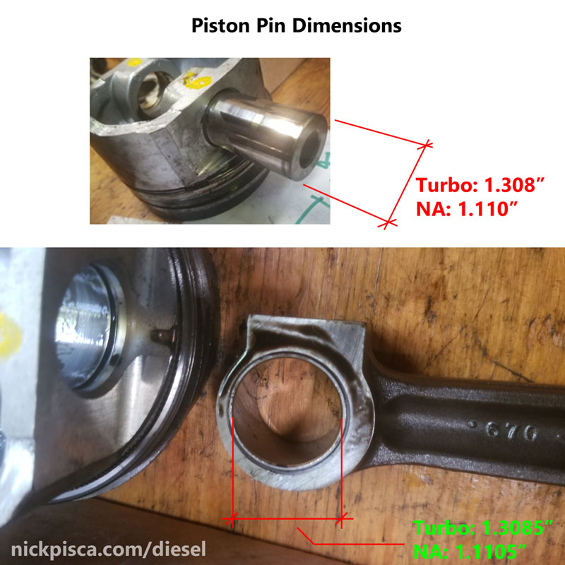
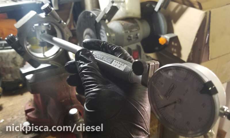
One by one, I moved the pistons on to their respective connecting rod, carefully measuring each to verify they all fit precisely together without issues. Then I measured their respective crank journal sizes, inserted new bearings in the rod and cap, torqued them down in my vice, and then measured the bore on them to verify they fell into the proper oil gap spec.
All of this measuring, torquing, sizing, and installing was described in the Connecting Rod article located here:
Before I could install these perfectly calibrated rods and bearings, I had to install the ’88 crankshaft in the ’94 block. I turned my engine upside-down on the stand, and then conducted the bore measurements on the crank mains. The process is simple: clean off the empty crank mains, insert new crank bearings into the block, torque them down to spec, and then measure the bore against the diameter of the crank journals.
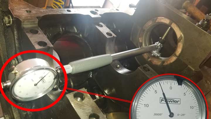
This process is detailed in the end of the Crank Bearing article mentioned here:
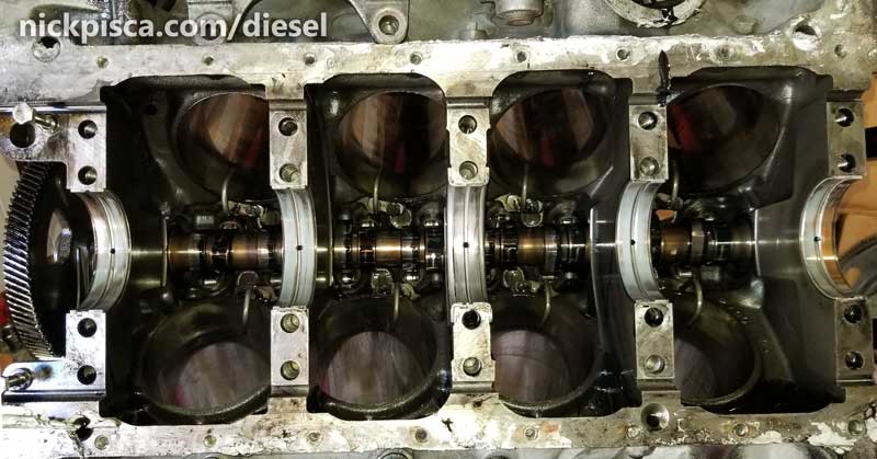
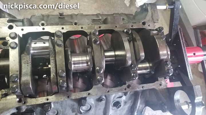
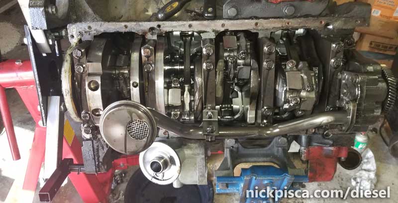
With the bearings checked out, I disassembled everything, installed the ’88 crank into the ’94 block, and retorqued all the mains back down, careful to properly lube all the surfaces with engine oil. Since my plan was to run this engine shortly after I rebuild it, I didn’t bother with long-term storage assembly lube. I just used regular Rotella diesel-rated oil to lube up all the mains, and then deposited the crank into place. It fit like a glove. And as I torqued down all the main bolts, I occasionally turned the crank just to make sure it didn’t seize up on me.
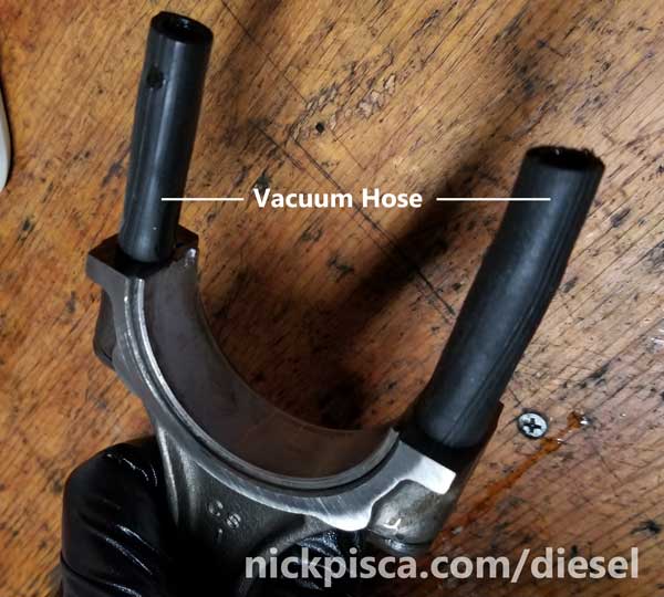
 Using some clever tricks from the internet, I was able to reinsert all the pistons and rods without scratching my crank journals. I highly recommend buying a piston-insertion cylinder to aide in the compression of the rings for insertion to the engine bore. Also, the use of rubber vacuum hose (instead of fuel hose, which has too thick of a hose wall), allows for the smooth insertion of the rod threads around the crank if you are working on this on your own without a helper.
I explain a lot more about the insertion of the connection rods and pistons into the chamber in this article:
7.3 IDI Piston Ring Gap Measurement, Custom Grinding, and Proper Installation
One by one, each cylinder fills up with horsepower goodness, and the hard part is almost done. I finalize everything with a double-check on the torques on the rod caps and crank main bolts, and the bottom end is pretty much good to go.
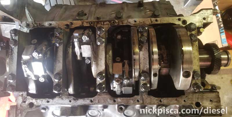
The last thing on the bottom to handle was the installation of the oil pump. This is a pretty simple operation, with three bolts and a nut on the middle crank stud. My ’94 oil pump was clogged with bearing shards, so I avoided reusing anything from that. My ’88 pump worked well, because it was strong enough to pump oil against the pressure of the coolant. So rather than buying a junk Chinese aftermarket oil pump, I stuck with the OEM ’88 pump. Maybe some day, I’ll take the ’94 pump apart and clean out the shards. I’m sure as long as it has the proper clearance tolerances, it’ll clean up fine.
Next, I figured while I had it all apart, I might as well do the front and rear main seals. If you have a press, it’s an easy job. If you don’t have a press, I don’t know how you can accomplish it with any specifications certainty.
I talk all about the main seal job here:
I forgot to mention that I lined up the marks on the crank and camshafts before torquing down the crank mains. Kind of an important task before you put on the front and rear engine plates.
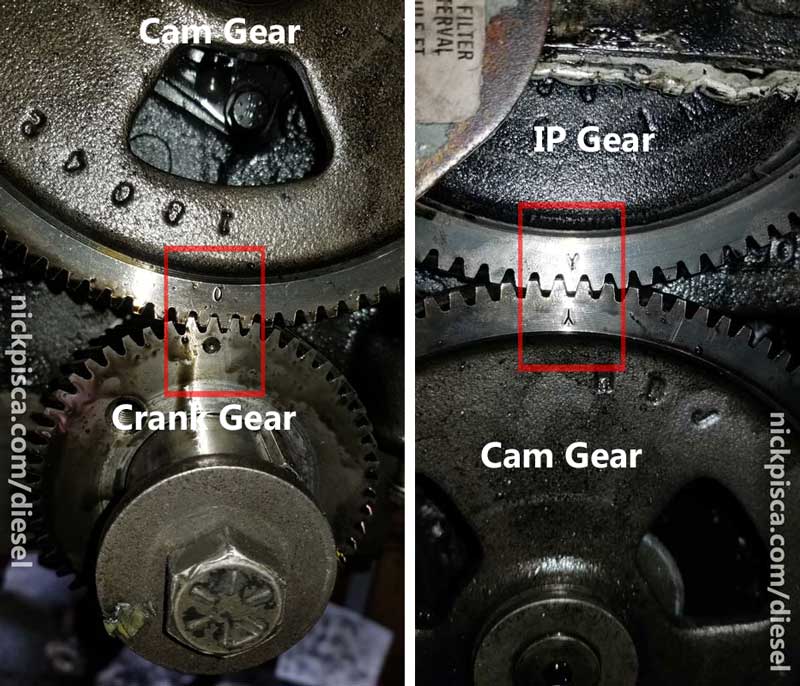
Aligning the IP Timing, Camshaft, and Crankshaft Gears on a 6.9 / 7.3 IDI Engine
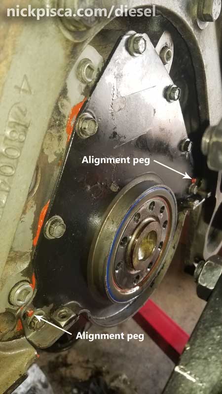
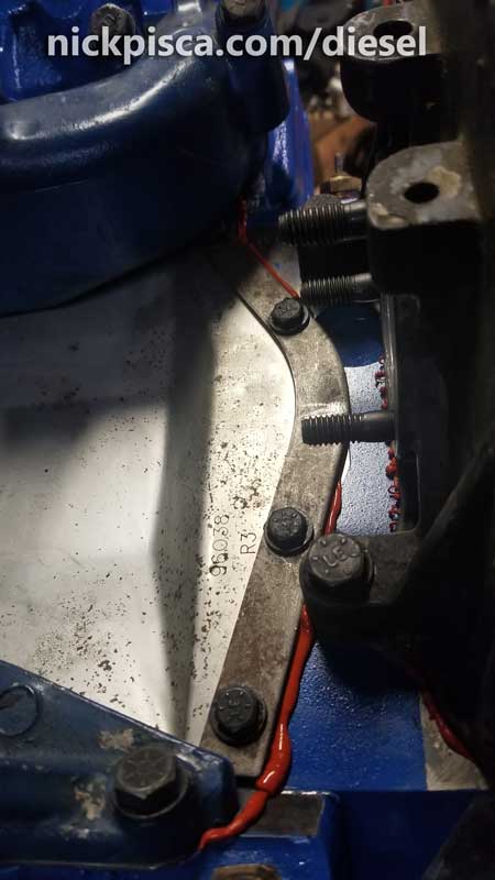
With a bit of finesse, I situated the rear plate on the engine, lining up the pegs, and with almost no required finesse at all, fitted the front plate on without issue. You can see how these plates were installed at the end of the front and rear main seal article.
The rear plate is a lot harder to install because the seal has to fit around the crank perfectly, whereas the front seal mates with the polished surface of the harmonic balancer, not the crankshaft. This means when the harmonic balancer slides on, it smoothly fits into the front seal hole, without the need for finagling the plate into plate. But that isn’t until I get the block painted.
The only thing left was to install the oil pan. But I wanted to paint the block with the heads on. Also, I wanted the pan, VC’s, and gearhousing to be black, the block and heads to be blue, and the accents to be red. However, if I put the oil pan on, I would inadvertently make it harder to make these separate colors. So, I put the damaged ’94 oil pan on, just to be a paint spray guard for the crank and other bottom-end components. The mechanics that checked out the ’94 block made the classic mistake of resting the engine on its IDI pan, which crinkled it up like a raisin. Now it’s only good for blocking the overspray, so it served an alternative purpose. But in order to get to painting the block and heads together, I need to put new HG’s on, insert the ARP studs, and get them heads on!
7.3 IDI Cylinder Head, Head Gasket, and ARP Stud Installation
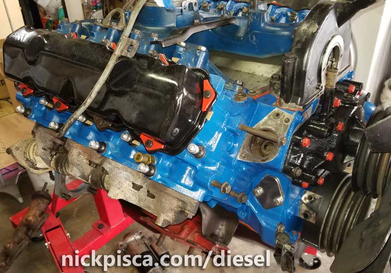
With the heads installed, the dummy oil pan in place, and I taped off all the mating surfaces (maybe a little overkill, because typical brake cleaner cleans off spray paint with ease), I gave the block and heads some High-Temp VHT primer and paint.
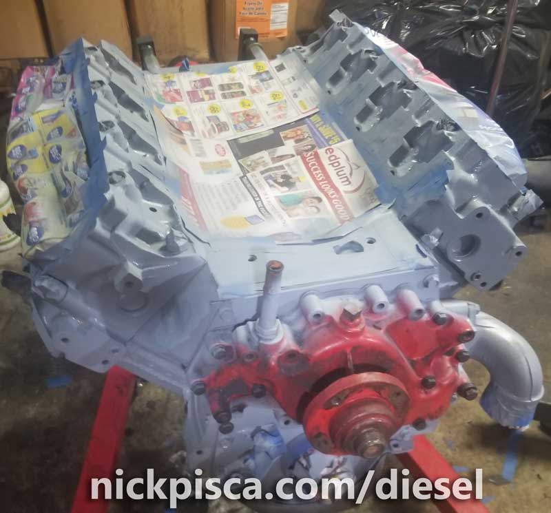
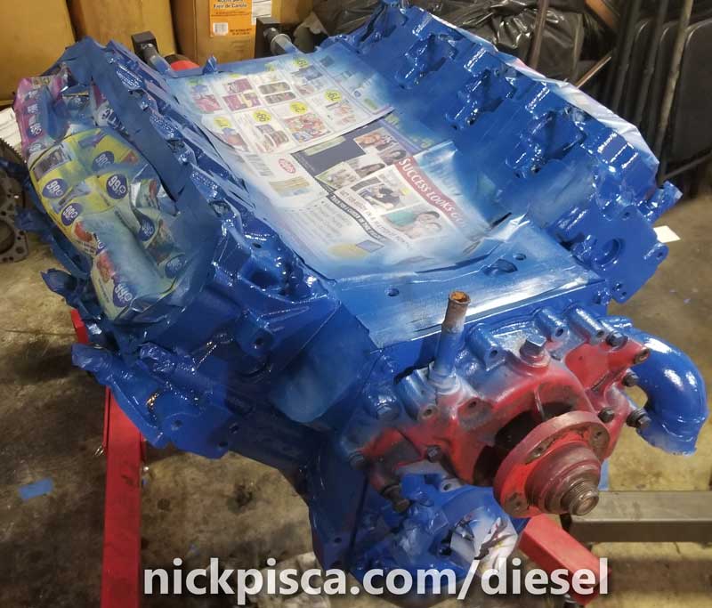
It was a bit of work to tape off all the head studs nuts, but I really want those to avoid the paint. I like the contrast of the black and blue. If you are wondering why my water pump didn’t get any paint, it was because on the 6.9, we installed a new water pump last year, that I plan to swap over once I pull the 6.9 out of my engine bay. Also, once that WP is out, I’ll give it a coat of black paint to match the VC’s, Oil Pan, and gearhousing.
With the front plate painted nicely, I took some time to carefully mount the harmonic balancer. For how I installed the Harmonic balancer, check out this article:
6.9 / 7.3 IDI Harmonic Balancer (Vibration Damper) Replacement Process
Also, I installed my newly-resealed oil cooler assembly. I’ve done that job so many times, I could do it blindfolded. Here’s the article on that deal:
When I installed my oil cooler, I made sure to do my mounting bolt replacement, because it makes it a lot easier to manage later in life.
Finishing Up:
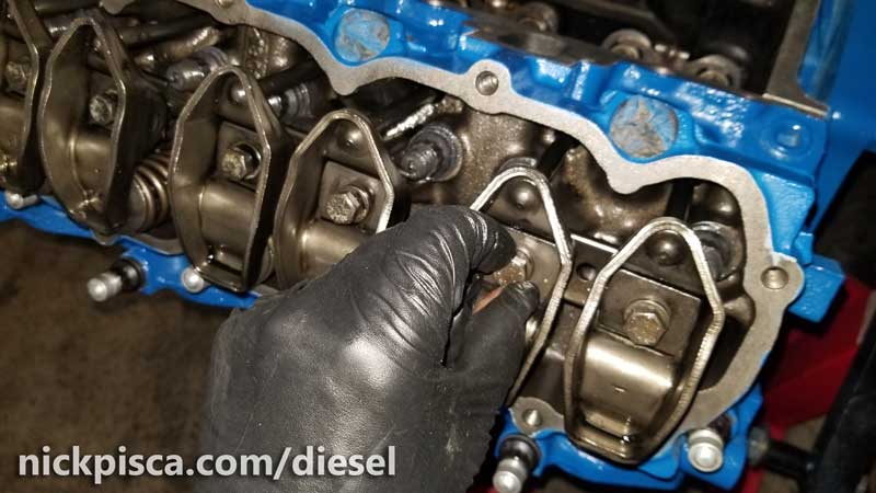
I tossed in the push rods after doing a rolling-check to make sure they are all straight.
Then I topped off the rocker arms and torqued them to spec. Since I had labeled and arranged them in boxes to match the previous order of the teardown, then they were pretty easy to reinstall.
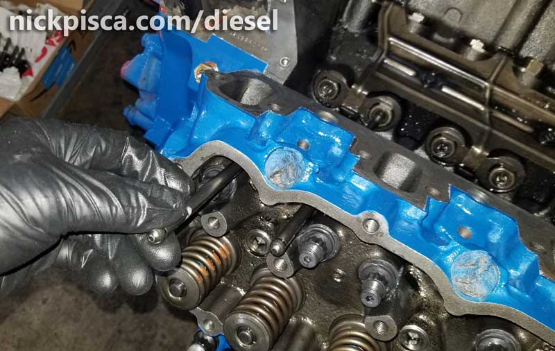
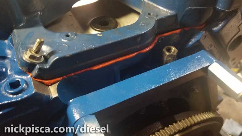
Next I installed the valley pan. Since this pan was unmolested and undamaged, I elected to clean it up and reuse it. It only has a few tens of thousands of miles over the last three years, so it should be ok to reuse. Also, as stated in the Head Gasket Article, I made sure that when I torqued down the studs, that they didn’t incur the clash with the rocker arm retainer. There is not a lot of room for error there.
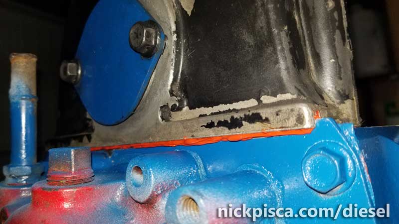
It requires a quarter-inch bead of sealant on the front and back, but not on the intake. There are few spots at the ends that need to overlap the intake holes, but refer to your shop manual for the dimension on that.
I plopped the intake on and torqued that according to the proper intake spec and pattern.
The installation of the intake and valley pan have to be closely coordinated. The sealant gets pressed on when the intake is torqued into place, so if you wait too long, the sealant will harden under the valley pan, and won’t spread to make a decent seal.
Just a heads up, the intake bolts are different sizes. This means to keep track of the sizes, or look at the elevation of the intake holes to show which are taller and which are shorter.
While this is going on, I’m also installing the IP gearhousing cover. This requires some clean up and preparation, so that the groove under the gearhousing matches the top of the front plate.
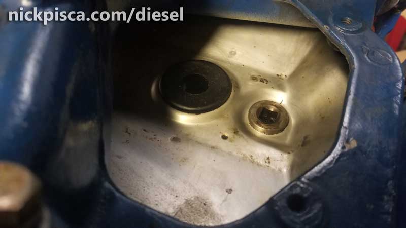
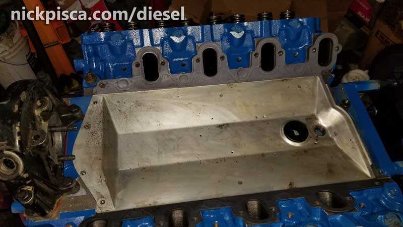
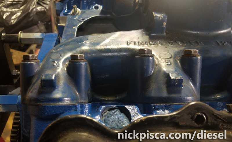
Also, the valley pan has a special NPT fitting that allows for drain to the rear of the engine. This fitting needs to be installed with RTV to ensure water or diesel doesn’t flow into the crankcase. If your IDI has a turbo, then there is a large black grommet designed to allow for turbo oil drainback. If you have a standard CDR attached to the intake, then there is a special CDR adapter fitting (not shown in the image above).
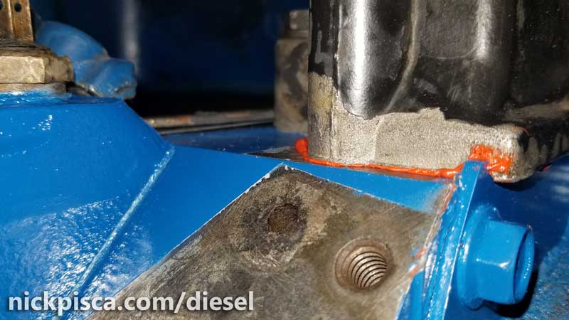
Failure to line it up, will lead to the aluminum gearhousing to crack. I’ve seen other gearhousings that have cracked from PO’s, so they are not very durable. Also, the gearhousing bolts require RTV on the threads, according to the spec, because they pass through into the crankcase.
When installing anything with RTV, be sure to install the component with light pressure, let the sealant become tacky, then torque it down. The tackiness allows for the gasket maker to provide a better seal. If you torque it down without letting it semi-harden, then it’ll just squirt out like toothpaste and not provide a solid seal.
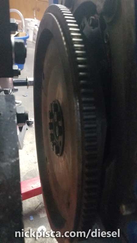
I also installed the C6 flexplate/flywheel and the starter. This is pretty minor and the mounting bolts to the crankshaft should have thread-locker since this is a vibration/rotation component.
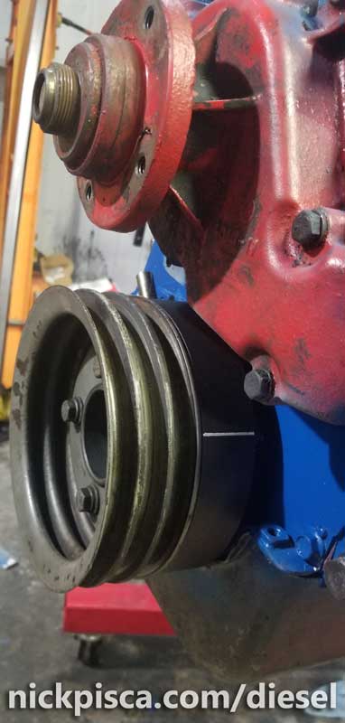
I also installed the pulley on the front of the harmonic balancer. In a strange series of events, I installed it wrong. First, since the balancer seemed about 1/8″ further from the oil pan than the previous harmonic balancer, I moved the spacers around so that it moved the pulley 1/8″ closer to the balancer. This way, once the water pump was installed, then it would match the v-belt alignment better. However, as I later learned once I properly installed the final black-painted oil pan, my measurement was from the crinkled oil pan that wasn’t properly torqued down. So later, once we had the proper 6.9 waterpump installed, it was clear the original spacer layout had been correct, so we revised it later.
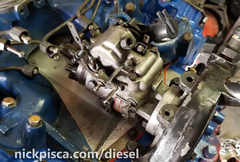
I installed the IP and tried to align the timing as close to the original mark as possible. I know this doesn’t mean much, but I figured close would at least afford me something between 2-12 deg BTDC. Ironically, once I installed this in the van and properly timed it, I would find out my timing was actually around 18 deg BTDC! I’m just glad it started.
I don’t have a picture, but after this, I turned the engine on its side and installed the newly-painted oil pan with plenty of RTV sealant. For a huge project like this, I recommend getting the caulking-gun tube of RTV, which is far more superior to the toothpaste-style tube that inevitably fails. Using a caulking gun to lay the bead for the oil pan made it a simple job.
Getting it Started:
For a project like this, I want to make sure it works before I install it in the van. With a van project, it is nearly impossible to make changes to the engine once it’s mounted in the compartment. So I need to know if all this work rebuilding the engine was successful. I researched a bunch of videos trying to get a primer on how to start an IDI on a stand, and to be honest, there wasn’t anything very clear or concise. So I felt inspired to use this moment as an opportunity to make my own “engine stand video,” showing every little step on how to fire up this beast without an engine bay.
Here you go:
What the video doesn’t show, is the amount of time spent trying to crack and purge the air from the fuel lines, that took a very long time. It drained my batteries, and I had to get some help from my idling van’s batteries. Regardless, it started up very nicely, so I’m confident my compression is excellent, my timing is pretty good, and overall, the rebuild is a success. I’ll be driving it all summer to test out its efficacy and performance.
After it ran ok, I did some cosmetic things. Also, there were some things that needed to be transferred from the 6.9 to the 7.3 once we pulled the engine, like the waterpump, driver’s side VC, and some other things.
Also, I’m wrapping up a lengthy timelapse of the installation of this engine in my van, with audio commentary by me and my mechanical partner on these Diesel and Biofuel projects. I’ll post it here as soon as he approves my director’s cut.
If you liked this article, you’d also like to see the time-lapse video and audio commentary of the engine swap:
Time Lapse Video and Audio Commentary of 6.9 to 7.3 IDI Engine Swap in a Van
No warranty. You are responsible for your vehicle. For novelty use only. Not responsible for anything or anyone. Not responsible for damage to your vehicle, you, or anyone or anything.
Copyright 2000-2018 Nick Pisca 0001D LLC