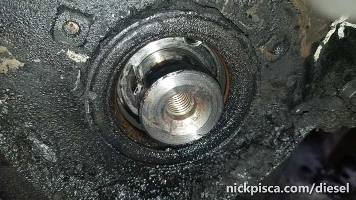
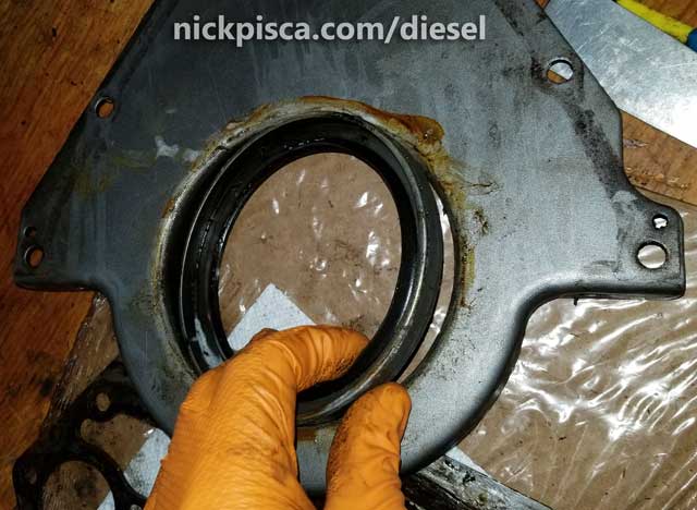
One of the most common places for oil leaks on a 6.9 or 7.3 IDI engine is the front and/or rear main seal. The main seals are the composite rings that encapsulate the ends of the crankshaft, that keep the crankcase oil from gushing out of the engine. After a couple hundred thousand miles, these seals tend to get brittle, worn, or busted, which ends up letting a little bit of oil seep passed with every revolution of the engine. It builds up and gets a little out of control, like in this image below:
I started my seal job by first pulling my engine from the van. Here is an article detailing how I pulled a 6.9 out of a 1984 E350, and here is an article explaining how I pulled a 7.3 IDI out of 1988 E250 Clubwagon. According to the Ford Service Manual, there is a way to extract and insert new front and rear main seals with the engine still in the van, but GOOD LUCK. You might have better luck trying to hire a leprechaun to assist you. The front plate is fitted with 3 welded nuts to the front face of the front engine plate that supposedly allows you to use a special type of a Ford puller (Part number ZTSE-4130) to extract and install the seal without pulling the front or rear engine plates. But my question is, if you already have the harmonic balancer, pulley, water pump, and other front mounted accessories uninstalled, why not spend the extra few minutes just removing the front and rear plates, cleaning them up, putting in new gaskets and permatex, and of course, installing the front and rear main seals? You got it all apart, might as well do it right.
Pulling off the Front Engine Plate.
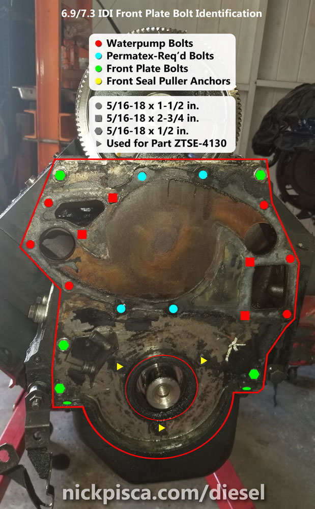
The front plate is held on by small bolts and basic gaskets. The Front Plate bolts are identified in green (in the image above).

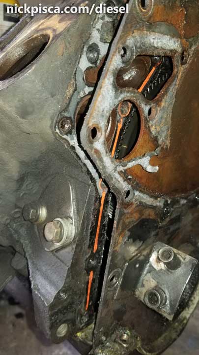
Gear housing damage, likely incurred with improper front plate removal or overtorquing the gear housing down without lining up the plate in the groove.
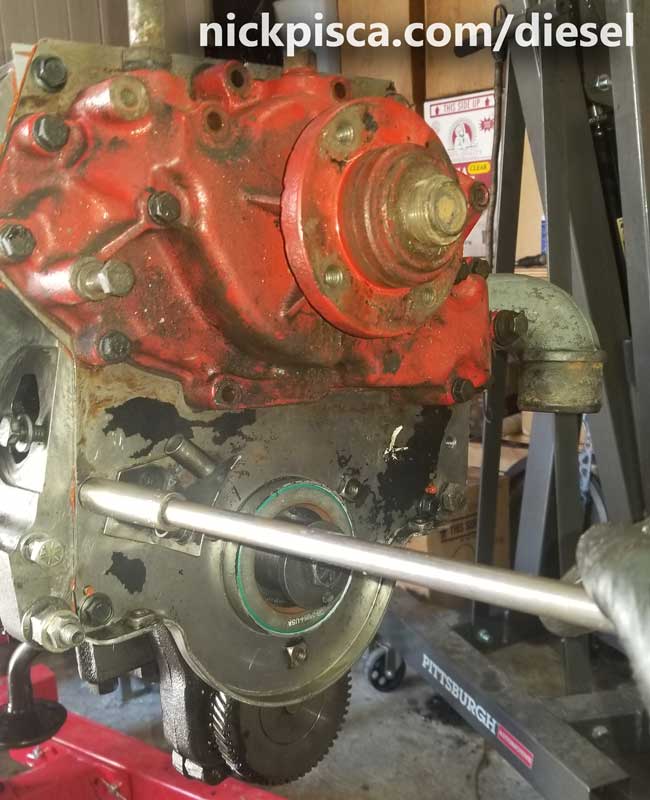
Before I could take off the front engine plate, I had removed my water pump and harmonic balancer (read the link to see how). Also, I had to pull of the IP gear housing. NOTE: The gear housing has a slot that allows the front plate to situate “into” the bottom of it. You won’t be able to extract the front plate without removing the gear housing. (NOTE: Attempting to pry the front plate off with the IP gear housing might break the housing. I once found an IP gear housing with two long cracks, originating from the ends of the front plate groove, all the way up the sides of the housing. It was basically trash, unless a person wanted to weld it back together. So pulling the IP cover is very essential to properly extracting the front engine plate.)
If you want to keep the exact location of the orientation of the IP, Camshaft, and Crankshaft gears, be extremely careful pulling off the gearhouse cover so that the IP gear doesn’t slip a tooth. Also, have a paint-pen handy so that when the front plate comes off, you can quickly mark the teeth on the gears to ensure the same installation sequence.
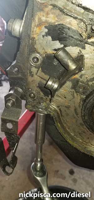
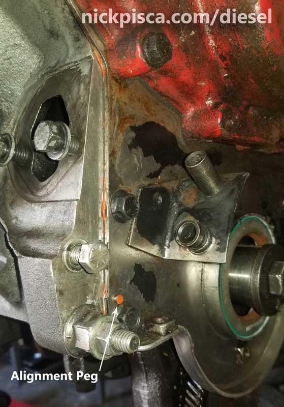
I carefully pulled back the plate from the block and pan (if still installed). It comes apart pretty easy if you have the oil pan already removed, but if the pan is still installed, it can really stick to it. Also MAKE SURE to remove the two bolts that thru-bolt through the oil pan and front and rear plates. See the image to the right for one of the locations of the oil-pan-front-plate thru-bolts.
The front plate has a gasket on the front for the water pump, but it also has a gasket rounding the bottom surface with the oil pan. It also has gaskets between the block and plate surface. Removing the front plate will require a few replacement gaskets.
I cleaned up the plate because it was covered in grease, diesel, old oil, and gasket material. After dousing it with brake cleaner and other solvents, it finally looked halfway decent. I didn’t spend a lot of time on this because I figured while I’ll be pressing the seals out and in, it’ll probably get oily and dirty, so making it super clean isn’t really a big objective. Later, when it is time to reinstall the plates to the block, making the surface as clean as possible is paramount to ensure the new block gaskets make a good seal.
Pressing the Old Seal Out.
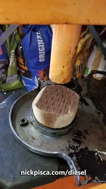
Ford wants me to buy some “Front Crankshaft Seal Installer” part number ZTSE-4130 to mush this old black seal out. I have a bunch of scrap wood laying around the garage, so I cut a cylindrical block and sanded it to approximately the size of the opening the front plate. Using my 20-ton press, I pushed the front main seal out relatively easily.
NOTE: There are two major things to remember when pressing out the front seal:
- Put the flat side down. Do not push it through the plate with the flat side up. It will likely deform the plate.
- Make sure the few nuts on that flat side are accounted for. Make sure to find a way to situate the flat side of the plate on blocks so that the welded inside nuts do not take any of the load.
 With the old seal out, I thoroughly cleaned the inside of the main seal from grime and old permatex. With the circumference thoroughly cleaned, I applied a thin layer of permatex to the plate side of the seal surface, then situated the new seal on top of the plate opening. AGAIN, I made sure my flat side of the front plate is down, and ensured that none of the interior nuts are taking any load.
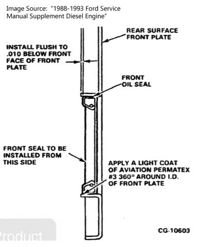
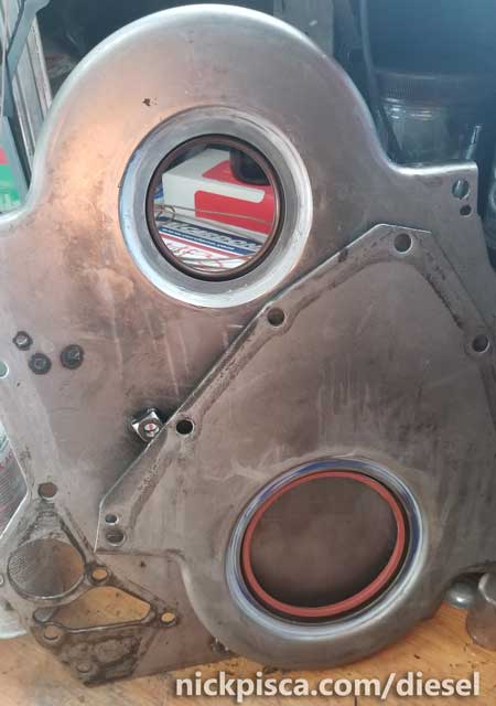
Orient the new seal on the so that the interior of the seal is setup like the image to the right:
Once the seal is perfectly level, I used the new cylinder block to start pushing the new seal into the plate. If it binds, then carefully work the seal so that it maintains a level to the surface of the plate. Do NOT force it into the plate. Binding will damage the seal and the plate.
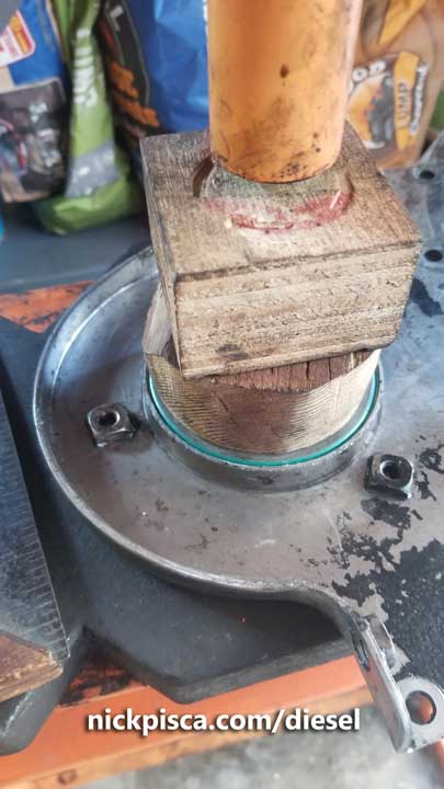
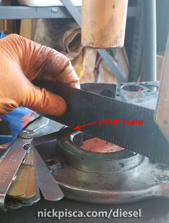
Push the seal into the plate far enough to the point that it recesses 0.010″ under the lip of the plate. NOTE: I made sure my seal didn’t go 0.010″ to the flat side of the front plate, but rather, I made sure it was 0.010″ to the lip. I used a feeler gauge kit and small metal ruler to make sure the measurement was right.
Naturally, as I pushed the seal into place, some of the permatex scraped to the underside of the plate. Using a clean rubber glove, I smoothed out the permatex so that it didn’t rise above the surface of the interior of the plate. This did two things: 1.) it made sure none of the sealant would extend beyond the specifications of the interior of the front plate, and 2.) it would provide some additional protection in case the sealant on the interior of the cylinder didn’t mate well.

Reinstalling the front engine plate is the reverse of uninstallation. New gaskets and sealant need to be installed and proper cleaning of the mating surfaces is paramount. There are plenty of places where oil and coolant can infiltrate, so clean gasketed surfaces are crucial.
Rear Engine Plate Removal:
I’m showing how to pull the rear engine plate off, from an engine on a stand. I’m sure there is a way to do this with the engine still in the vehicle, but I suspect it is really a PITA. (Off the top of my head, it would be something like, chock the tires, undo the torque converter bolts from the flex plate, pull the drive shaft, support the engine, support the tranny, undo the tranny mounting bolts, undo any exhaust in the way, slide the tranny back as far as possible [much easier to do in the van than the truck], and then undo the flywheel/flexplate to access the rear engine plate. That’s a freaking job.) So for the purposes of this article, I’ll be focusing on the process of taking off the rear plate, extracting the rear main seal, and putting it back together.
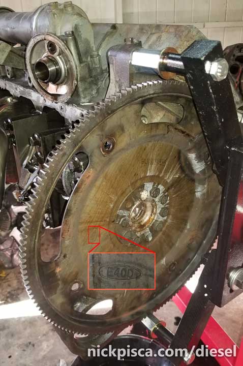
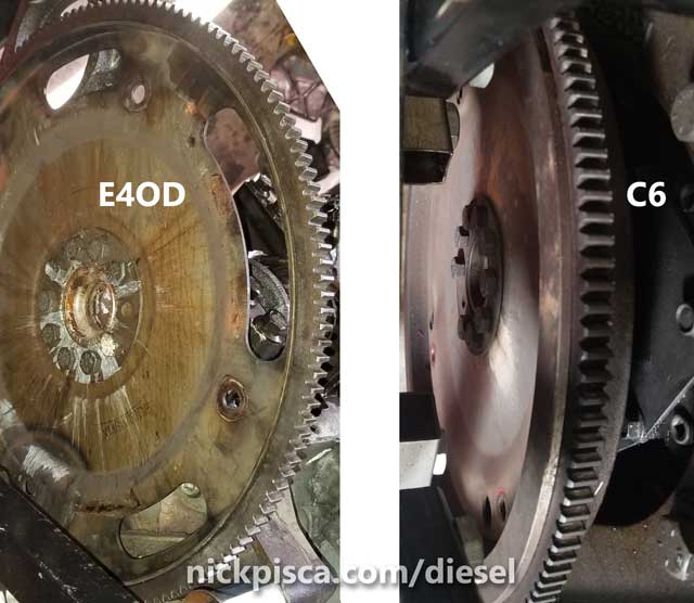
Depending on the year of your IDI, you might have an E4OD or C6 tranny. Both have different flexplates and spacers that mate with the torque converter in the transmission.
First I undid the flexplate (a flywheel for an auto transmission) for the E40D tranny from the 1994 7.3. It is mounted directly to the rear of the crankshaft with 8 bolts. There 9 holes (one hole is used to line up the flexplate).
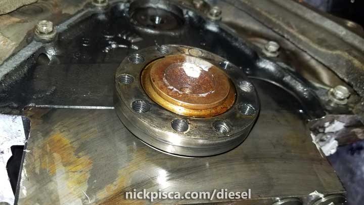
Unlike the harmonic balancer, I didn’t need a special puller to remove the flexplate. Just slid a 3/8″ drive long extension in one of the torque converter access holes, and unscrewed the bolts with a pry bar. However, behind the E4OD flexplate, there is a half-inch thick spacer between the plate and the crankshaft. (NOTE: the C6 transmission has a different space and flexplate.) It is solidly attached to the crankshaft, so at first, I was convinced it was one solid piece combined with the crank. However, with some wiggling and tapping with a rubber mallet, I was able to wiggle off the spacer from the crankshaft.

The C6 is basically the same thing, but instead of a thick spacer backer, it has a beefy flexplate/flywheel. The E4OD version is something like 1/8″ and the C6 is much much much thicker. Also the E4OD one has bigger holes in the plate, whereas the C6 version has almost no holes but the access holes for the torque converter.
The rear plate has 7 small 1/2″ long bolts that lock it into place. Once you get all the other crap off the engine or pull the tranny away, it’s a pretty simple procedure.
Getting the E4OD flexplate off and the rear engine plate:
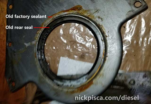
Using the 20-ton press (just like the procedure shown above with the front plate seal, with a special cylinder wooden block), I popped the old seal out of the rear plate. I kept the flat side down, making sure that the plate stays flat.
Just like the Front Seal installation mentioned above, the plate needed to be cleaned of all gasket sealant and other grime. Then the inside of the hole needed a coating of permatex, and the rear main seal could be pressed into place. Ford, according to their service manual, wanted me to buy some odd installer tool (#ZTSE-4131) to press the new seal into place. I just used another custom cylindrical wooden block that I made on the spot. I carefully pressed it into place making sure it wouldn’t bind or warp the rear plate.
Once it was nearly in place, I checked the service manual for the offset from the plate lip. In the Front Plate instructions, they mentioned the seal needed to be 0.010″ from depressed from flush from the top. However, there was no depression dimension mentioned in the manual for the rear seal. So I situated it as close to what it was from the previous seal.
With a clean latex glove, I smoothed out any excess permatex. With the plates cleaned up and the new seals installed, I set them aside to properly dry. I need to finish up installing the crankshaft and rods and pistons before posting the reinstallation to the block process.
Reinstalling the Plates to the Block:
The rear plate is the simplest to reinstall, but it does take some finesse to situate the rear seal around the end of the crankshaft. Since the interior of the rear seal faces inward, I have to kind of stretch the rubber part of the seal round the metal. It is a pain. I can’t use a thin metal tool to warp the seal around the metal, because it might scratch the surface and/or damage the seal. So here is how I accomplished it:
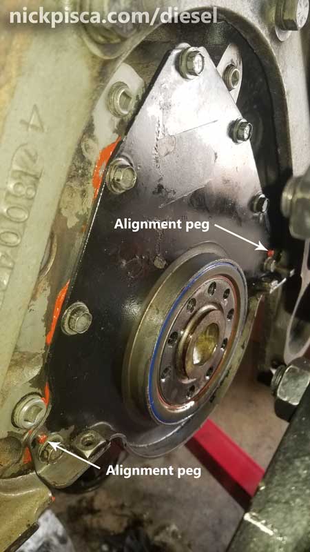
I lubed the end of the crankshaft with engine oil, and also lubed the rubber on the seal. I practiced twice putting the seal around the crank before even attempting this with permatex and a seal. The last thing I need to do is gum up my gasket trying to do this on a first attempt. So I did some practice runs first. With the mating surfaces slicked up with oil, I lined up one of the “Alignment Pegs” (see image above) and worked the bottom of the seal around the crank first at about a 45 degree angle from the floor. Then I slowly rotated the plate to meet the block surface, all while slightly pushing the plate upward. This upward movement pushed the lower lip of the seal down, which afforded me a little more room to squeeze the top of the crank inside the seal.
It takes some practice, so I highly recommend doing some dry runs prior to applying the permatex and gasket. Trying to align the two pegs and fit the seal around the crank is not that easy once you have the sticky permatex and you are on the clock. When I was ready for primetime, I coated the rear plate gasket in a thin layer of red RTV permatex and stuck it to the back of the plate. Then I situated it on the back of the engine carefully negotiating the seal. I tightened seven rear plate bolts finger tight so that the permatex can get tacky, then an hour later, I torqued them down to 24 ft-lbs.
 As for the front plate, it’s a lot easier to put on, but there are lots more bolts. However, prior to installing the front plate, IT IS PARAMOUNT TO MARK THE CAMSHAFT GEAR. Once the front plate is on, it is nearly impossible to find the timing mark on the side of the gear to match up with the IP Gear. For information on this process, read this short article.
The front seal doesn’t seal with the crankshaft, but rather the finished interior cylindrical surface on the harmonic balancer. I’m a bit anal about making sure the gasket maker sets up with the proper torque, so I coated both left- and right-gaskets for the front plate with permatex, and set them to the back side of the plate. Then I slid the plate on the alignment pegs and set the main plate bolts (see the bolt diagram at the top of this article for locations) to finger tight. After an hour, I finished torquing them down to the same spec as the rear plate.
I’m not satisfied with the five plate bolts making a solid connection to the interior parts of the gasket, so I temporarily installed a spare water pump with all its respective bolts in place. This will distribute the load of all the gasket surface equally. Once the gasket and sealant have set a few days later, then I can replace the temp water pump with the proper new water pump that I have set aside for painting.
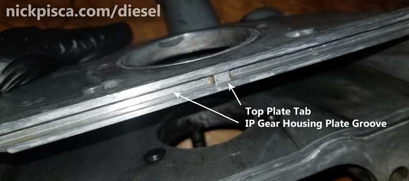
The top of the front plate has a notch in the middle. This is to align the IP gear housing for reinstallation. Keep this in mind when reinstalling the IP gear housing. Misalignment WILL lead to cracking of the aluminum housing once it is torqued into place.
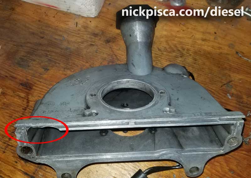
In my collection of IDI parts, I have come across several IP gear housings that were improperly installed, and incurred severe damage. Here is a picture (below) of a gear housing that not only broke, but it likely chipped off into the crankcase, which could have resulted in cam- or crankshaft-gear damage.
To learn more about the installation of the IP Timing Gear and the Gearhouse cover, read the article about the gear system.
Aligning the IP Timing, Camshaft, and Crankshaft Gears on a 6.9 / 7.3 IDI Engine
Once the IP gear is properly encased in the IP gear housing, and the front plate is fully properly installed and the sealants have dried, then the installation of the Harmonic Balancer can be accomplished. Visit this article for more information:
6.9 / 7.3 IDI Harmonic Balancer (Vibration Damper) Replacement Process
The harmonic balancer has a smooth cylindrical shaft on the interior that mates with the front main seal. Unlike the rear main seal which requires some finesse to situate around the crankshaft, the front main seal easily conforms to the harmonic balancer’s shaft quite nicely, without any complexity. The aforementioned article explains how to screw on the balancer with a 5/8″ threaded rod.
No warranty. You are responsible for your vehicle. For novelty use only. Not responsible for anything or anyone. Not responsible for damage to your vehicle, you, or anyone or anything.
Copyright 2000-2018 Nick Pisca 0001D LLC