I thought I would finally post the pics of my in-progress Head Gasket job on my 1988 7.3 IDI Clubwagon. I’m attempting to do what IDIJohn (and I think Macgyver) did a while back: Pull the heads with the engine still in the van. Here is the link to IDIJohn’s HG thread: https://www.ford-trucks.com/forums/1…me-in-van.html
IDI Truck guys probably don’t know how hard this job is. Overall, it’s been pretty awful, but not necessarily impossible. Update as of March 15, 2018, I have also done this head/head gasket/head stud job on an engine stand, and the write-up is located here. It was substantially easier, but shouldn’t deter anyone from doing the head job in the van.
Some background: I have the Hypermax Turbo Van Kit on this van. After about 25K after the turbo install, I started seeing oil in the coolant. I changed the oil cooler (twice) and both times the oil content increased. I checked other areas, but I guess the HG is the next logical spot to look. I started this thread to organize parts and tools for the upcoming job: https://www.ford-trucks.com/forums/1…-i-missed.html
Before pulling the engine apart:
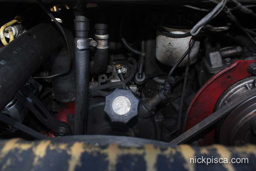
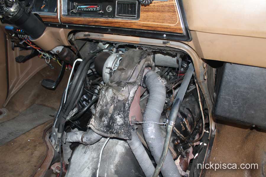
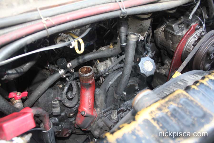
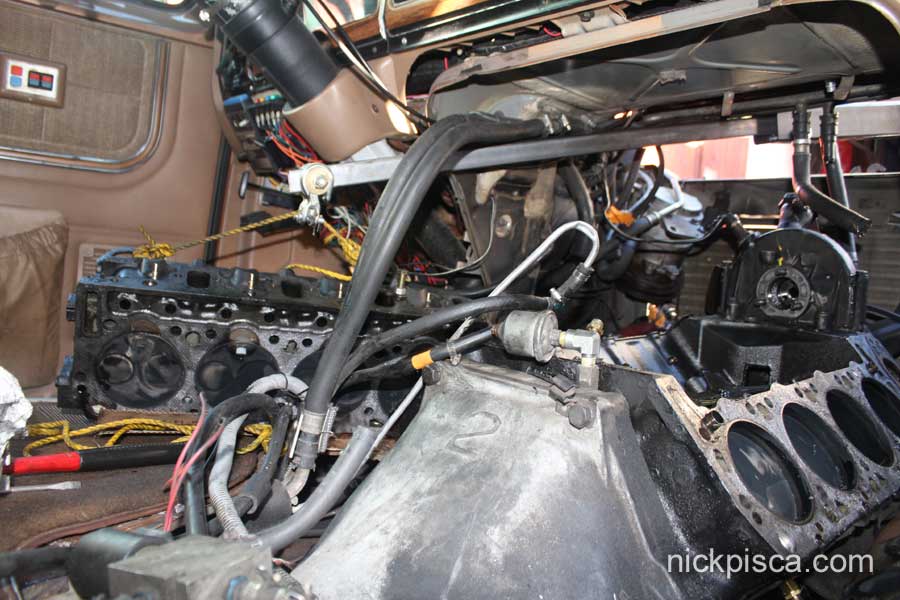
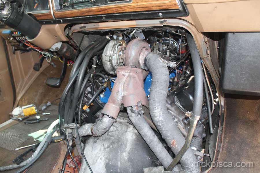
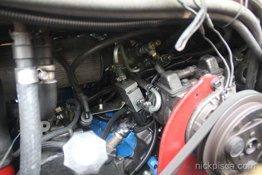
Here’s the rear of the engine. That turbo blanket has seen better days. And the doghouse rubs on the up- and down-pipes so my wrap is gradually wearing off in spots.
I soaked all the hard bolts (exhaust manifold, injectors, etc) with penetrate oil days before the tear down.
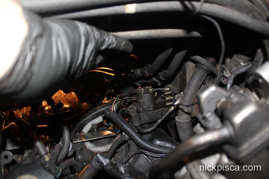
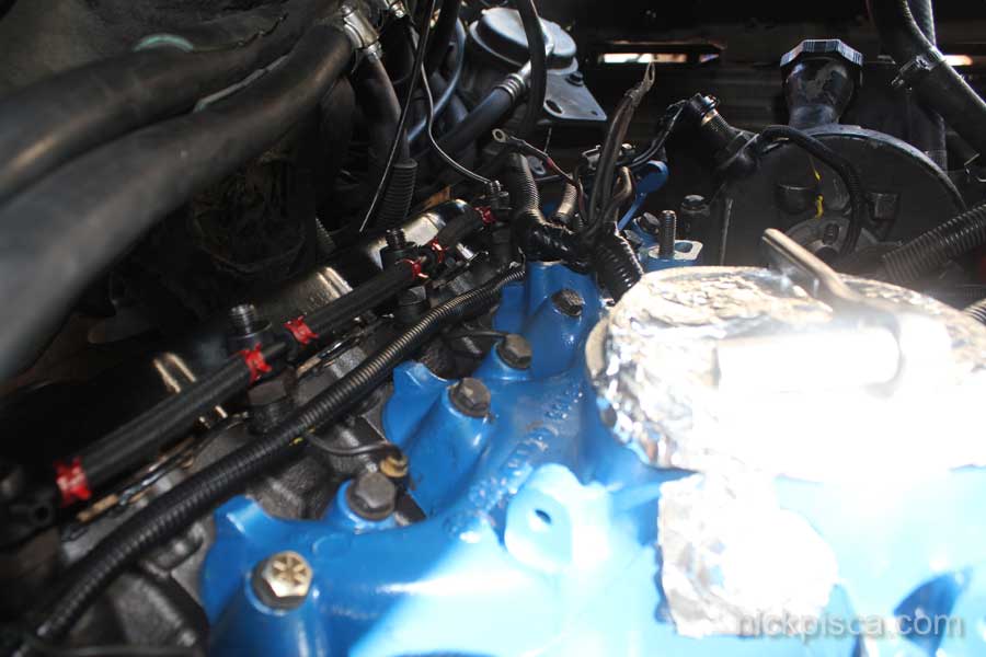
I took several pictures of the electrical and fuel lines to make sure I can put it all back together. Here is just one of the photos, this one showcasing the locations and orientations of the injector lines.
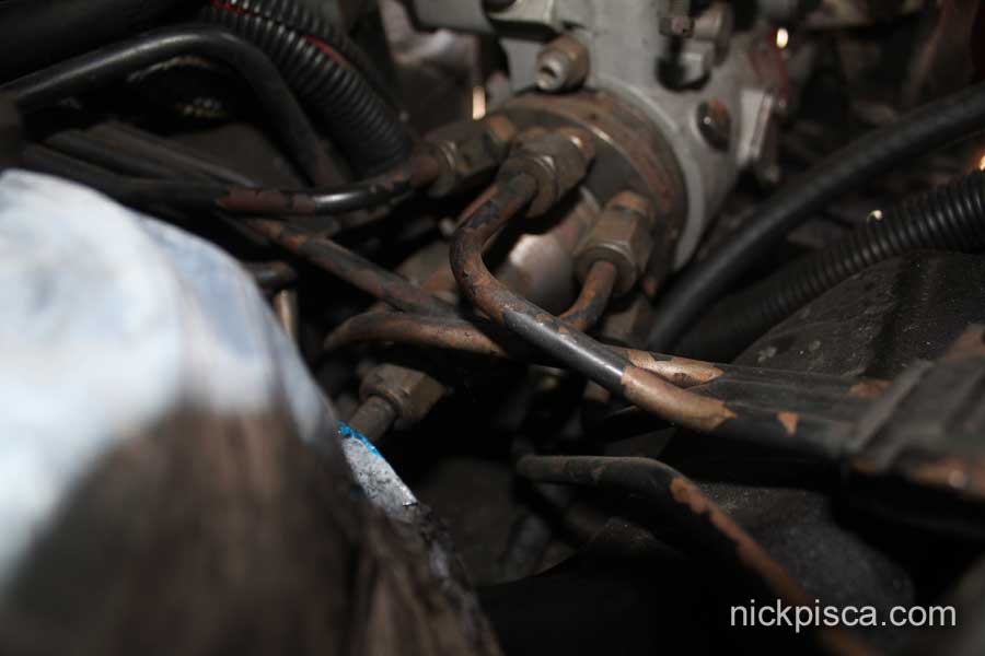
Update March 2018: I have since made an article the details the location and position of all injector lines at the pump, so that I don’t have to make crude photos of this system. Feel free to read up on the diagrams I’ve made here:
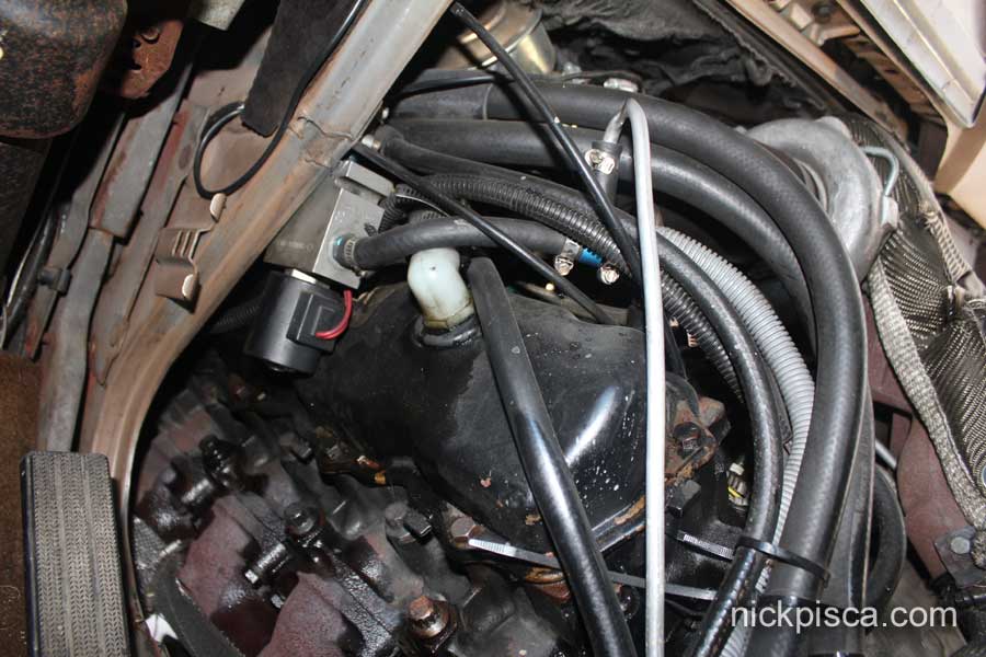
I took out my 3G alternator and vac pump on the passenger’s side of the van.
I was able to remove the AC pump bracket and slide it to the side without disconnecting the AC system hoses, thus preserving my r134. I also removed my radiator, in the hopes that it would allow me more room to work. Lastly, i was able to shift my PS pump lower to get it out of the way. I don’t have a good pic of that unfortunately, but what it means is, I don’t have recharge my AC and I don’t have to empty the PS system.
Next is to remove the Diesel filter head and the Hypermax mount for the moved glowplug controller. (you’ll have to undo the 2nd and 4th injector lines).
IP Removal:
You might want to mark the top of the IP where it connects to the gear housing. I used a dab of bright paint so I can line it back up again. I should have photographed that, but oh well. You need to undo the injector lines at the injectors, then undo them at the back of the IP. I ended up not undo the injector lines on the IP, and pulled it out IP+lines as one piece. Before you pull off the IP, undo the return hose on top.
Then remove the front plate to access the 12-point bolts. Remove those, then undo the 9/16″ nuts connecting to the gear housing studs.
Pull back and up. If you leave the injector lines on the IP, it’ll be a tough extraction. It barely fits between the intake manifold and the gear housing, and then it hits the top of the engine compartment ceiling. If you take the injector lines off, it is a PITA to get to those lowest lines.
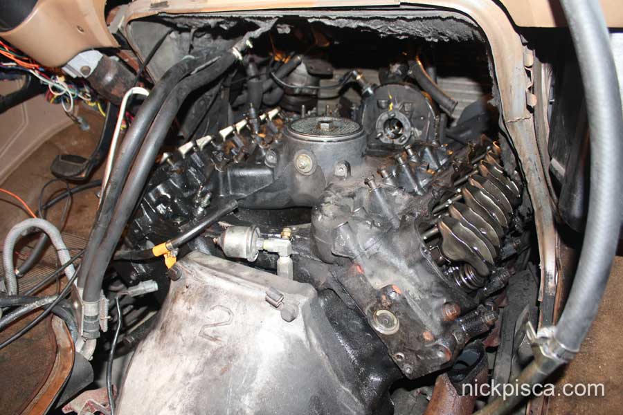
Pull off the valve covers.
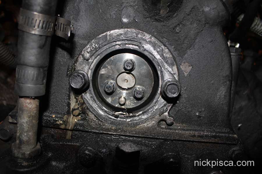
In the photo above, you can see the IP gear. As long as you leave the gear housing on, it will maintain its position in the timing and hopefully, i can reinstall the IP without issue. If you take the gear housing off, then you might want to search this forum on how to time your engine.
Here’s a pic from the doghouse side:
Next I pulled my injectors. 1″ wrench with a pipe. I used some liquid wrench to make the job easier. 7 injectors came out without much effort.
However, 1 injector was TERRIBLE. I let it soak overnight. And even then it required a 2 foot extension pipe on my wrench. I literally broke the pipe so I had to get a second one. I managed to get the threads undone, but it still was stuck, just spinning in place. I ended up using some Seafoam liquid to break up the carbon. That helped a lot, and using a 7/8″ open ended wrench as a prybar upward, I turned it with my 1″ wrench until I worked it upward and out.
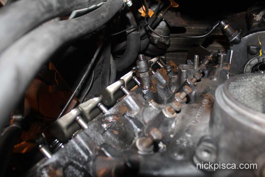
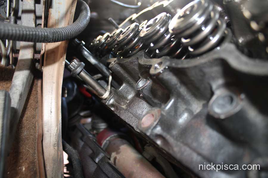
The clearance on both sides of the engine are TINY. The driver’s side is close, but the passenger side is VERY CLOSE. You can wiggle the valve covers off, but it is tight.
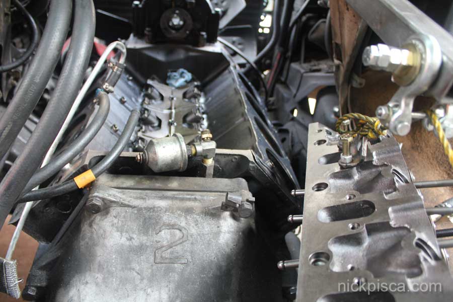
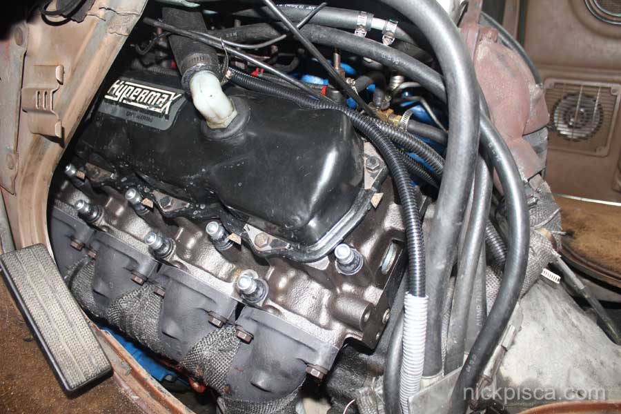
Here’s a picture of the passenger side head from inside the van looking toward the front.
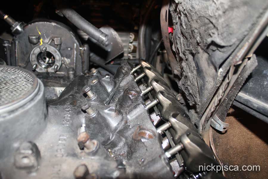
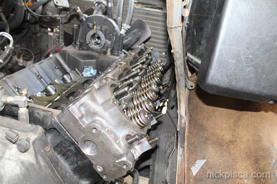
Here’s the driver’s side from the inside the van:
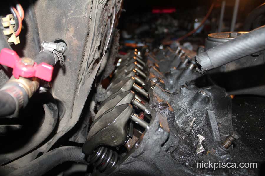
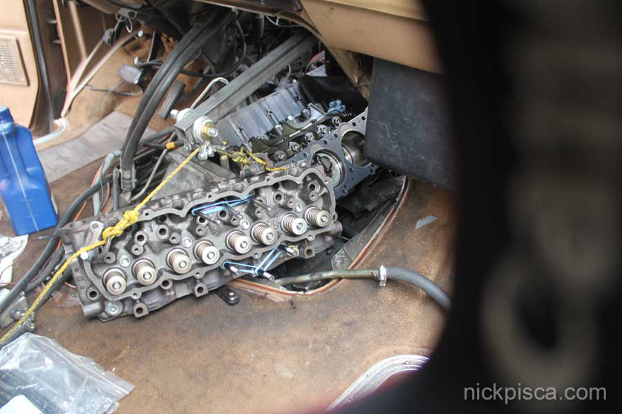
Pulled the valley pan off. Then start removing the rocker arms to extract all the head bolts and rods. In the van, not all bolts and rods will be able to be pulled. A few will have to stay in the head, and you’ll need a rubber band to hold it up. (It should be noted, I’m doing this whole job solo.)
In the Hypermax installation, they tell you to punch holes in the valley pan. It was interesting to see the divots from the bottom side once it was out.
I decided to pull the passenger side Head first. It looked like it was going to be the worst. In the image above, you can see the two bolts and two rods that had to remain.
I didn’t show how I got it out, because I was trying to devise a way to do it. Eventually I made a solution, and did the head extraction, and then I photographed the driver’s side head job instead. My original plan was to use the shop crane to pull it out of the front of the van, but then a better plan emerged.
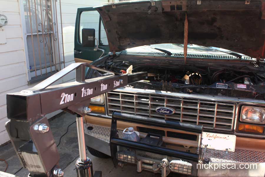
I constructed a simple steel extension to my crane. Then when I lift the head, I can just push it thru the doghouse opening.
Here’s the end bar that would allow me to balance the head very easily using a simple rope.
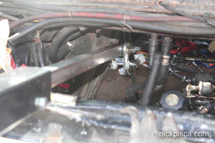
Here is how I was able to lift them up and back:
I was able to get all the push rods out of the drivers side head, but 3 bolts were not accessible. Here are the unlucky ones:
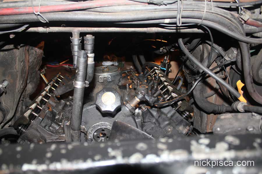
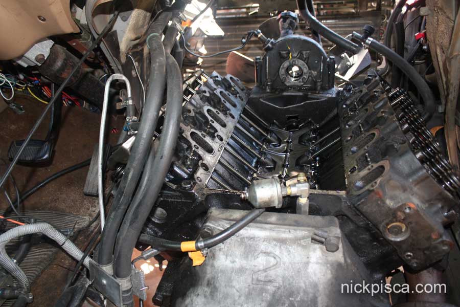
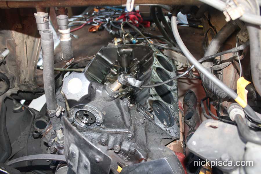
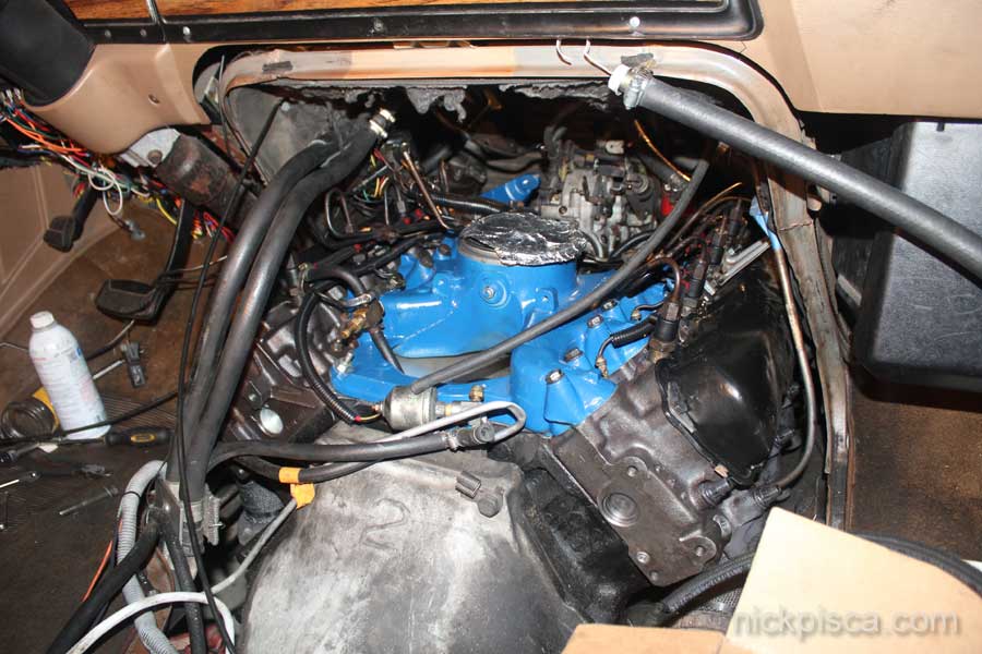
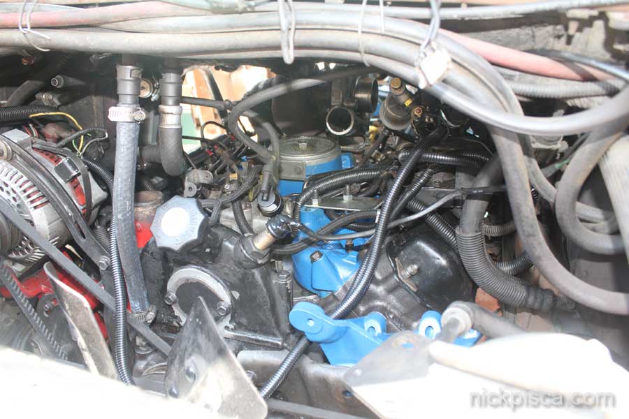
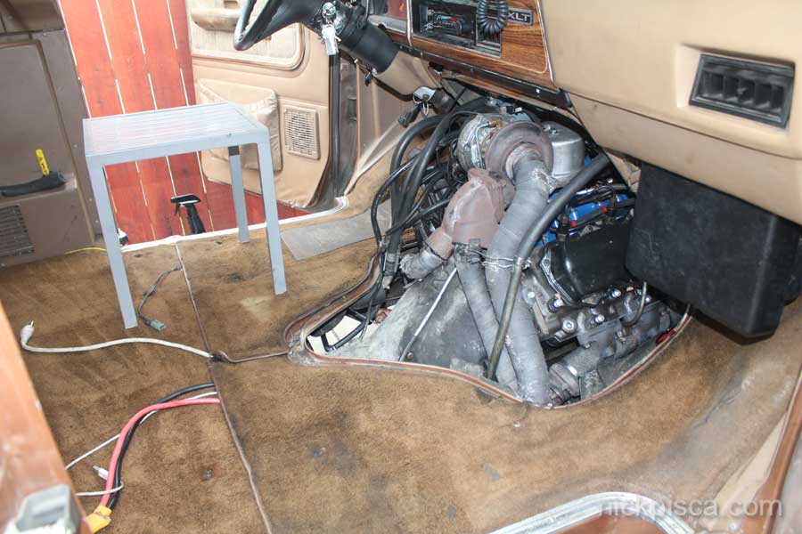
Here is the engine from the front:
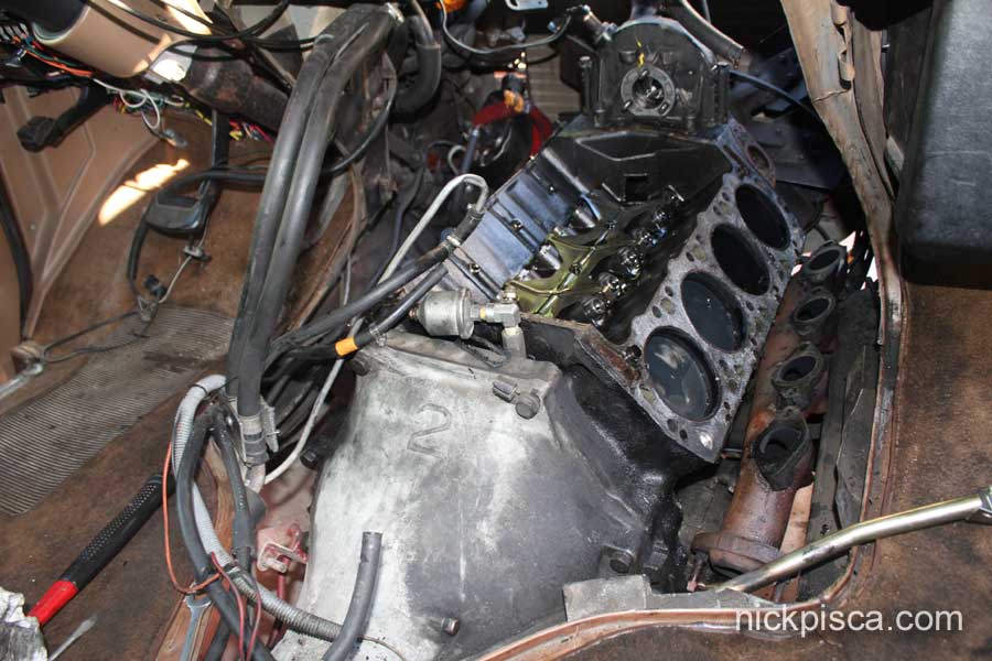
Here is the engine from the inside:
Just a reminder, I did this all on my own, so I had to be creative to pull it off. I won’t be that lucky on the reinstall. I will need a few helping hands to get the heads on, and after carrying them to the garage, they are not that heavy. If one person lowered the head from the front, then another lowered from the doghouse, it wouldn’t be too much and would be the safest way to install the head without damaging the gaskets.
I don’t have a decent picture of the exhaust manifolds coming off, but whatever, that’s pretty basic. The drivers side was pretty accessible, but the passenger side is very close to the frame rail and engine wall, so two bolts were nearly impossible to remove. Luckily, the soaking of the bolts must have helped and I was able to use a standard wrench in a tight space. if it required heat to extract, I would have been SOL.
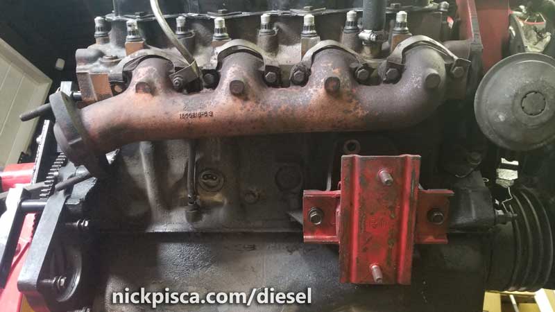
An image of an exhaust manifold (not from this project) on the passenger side showing the stud holding the oil dipstick tube.
Now that I have the EM’s off, I am going to wrap them with some spare exhaust wrap in the hopes to reduce the heat on the doghouse.
I forgot to add, I removed the oil dipstick tube when I undid the exhaust manifolds. Remember to reinstall the tube first, then reinstall the EM. if you forget, it is very hard to get it back in with the EM installed, especially in the van compartment. See image to the right for a shot of this, even though this image did not come from this project:
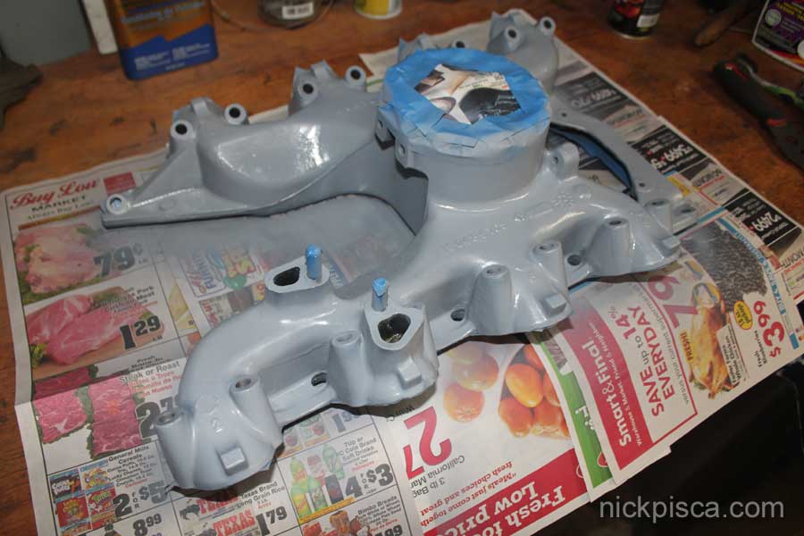
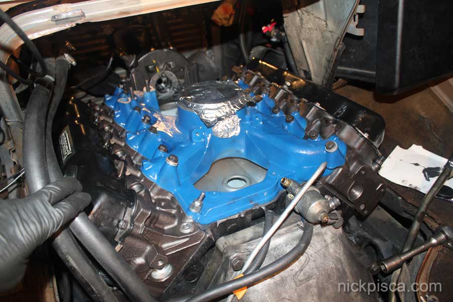
While I had the heads at my shop (EMS in Inglewood CA), I painted up my intake, several brackets, motor mounts, and valve covers. Here’s a pic of the primer stage of the intake painting. I gave it a few coats of blue paint after that, then coated it with some clear coat high-temp paint. If you bake your parts to cure the paint, don’t do it in your house–it’ll smell terrible.
EMS of Inglewood called to say the heads were warped in the middle, out of spec for thickness, couldn’t be resurfaced without exceeding the min spec, and the springs were on the bottom of spec strength. After some searching around, we called Diesel Cast Welding to build us a new set of heads, completely dressed. They arrived in about a week or so.
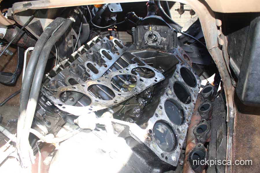
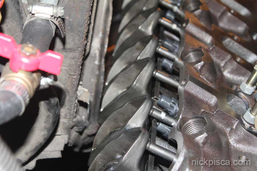
I cleaned up the engine surface as best as I could with the crappy gasket remover spray that Los Angeles allows. They don’t let you sell the good gasket spray here due to some environmental restriction. After about 20 passes on each side of the block, here was the condition of the surface:
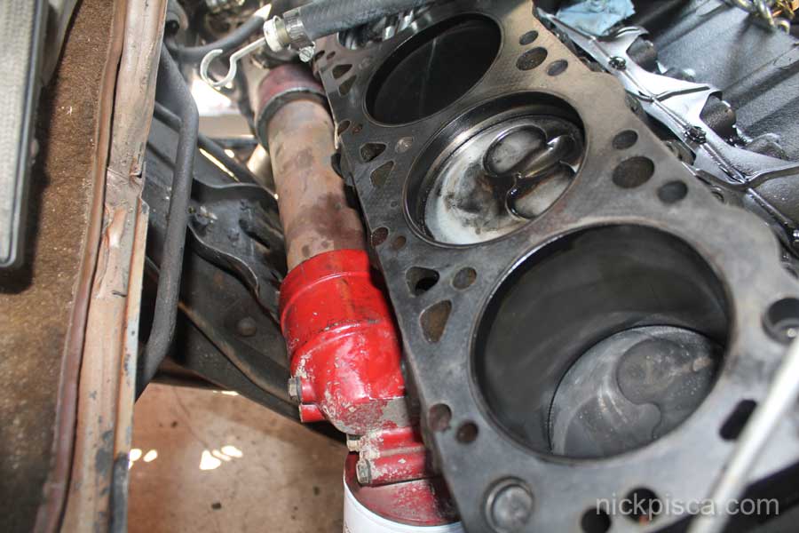
Pretty stained. But flat.
If you look closely, you’ll notice that in the previous picture, I have removed the motor mount under the oil cooler. This allowed me to tilt the engine to the driver’s side, thus allowing for maybe 1/2″ more room to insert the head. Since the ARP head studs I got from R&D IDI Performance are 7/16″ longer than the stock head bolts, they WON’T fit between the block surface and the walls of the engine bay. By tilting the engine, I get just enough room to put the head studs in. Here’s a pic:
Using the extension I made for the shop crane to remove the heads, I set it up to reinstall the new heads with the engine tilted.

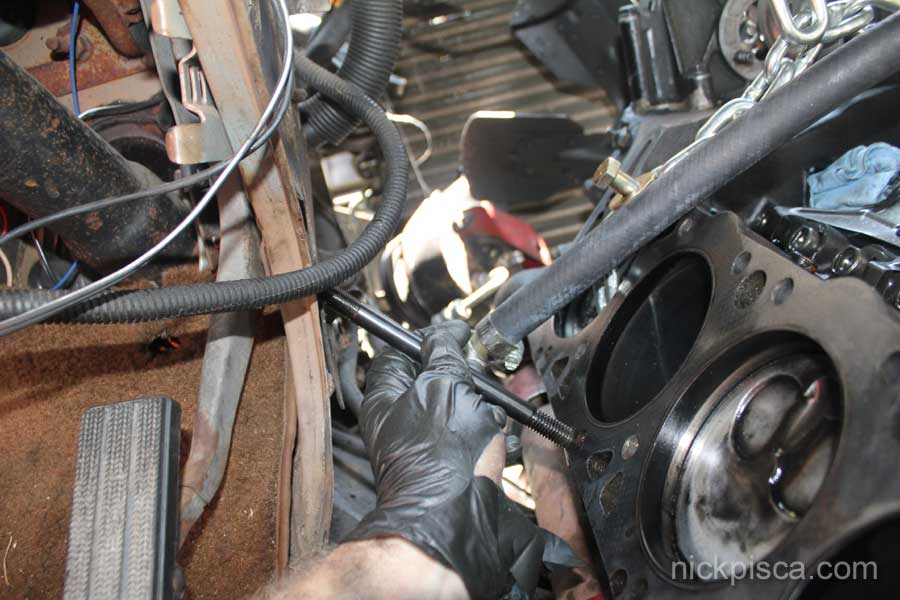
We dangled the head to match the angle of the block surface. My buddy carefully pulled and lifted the head with the shop crane, while I cautiously handled the head as to not nick the gasket. All while holding the studs and push rods with rubber bands, because if you don’t put them now, you can’t get them in once the heads are on the block. In the end, it had only a few 1/16th’s of an inch so it was a precision operation.
Once the head is seated, the other push rods and studs went in without much issue. Make sure to use ARP assembly lube when installing your studs so that you get proper torque readings. Since we couldnt’ install the head the normal way (1. install studs, 2. Slide HG over them to the block surface, 3. install head), we had to improvise the assembly lube. The best plan was to coat the threads in the block holes, rather than put it on the ARP studs themselves. That way we don’t push a bunch of Assembly lube onto the HG when we thread them thru the HG.
We torqued the studs down to 150 ft-lbs. R&D IDI Performance suggests this in their documentation, and we were a bit concerned that it would be possible to get that accomplished in the cramped confines of the van engine bay. But with enough 9/16″ sockets of different lengths was the key to reaching all of them properly. This definitely wouldn’t be possible without tilting the engine. In the image below, you can see the stud nuts tightened down to the 150 ft-lbs. Unlike the IH conventional head bolt torque spec (pictured below), we torqued them in the proper sequence, in intervals of 65-, 90-, 120- and 150-ft-lbs. We used the conventional torque sequence (shown below) though.
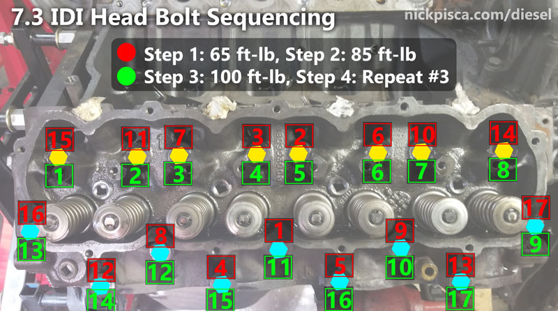
7.3 IDI Head Bolt Sequencing and Torque Spec
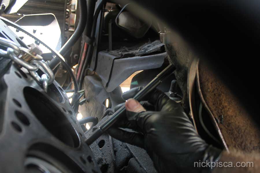
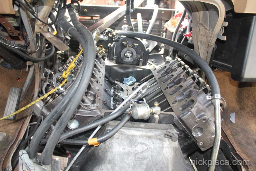
We put on the rocker arms and tilted the engine to the passenger side now. This will allow us to put the driver’s side head on with enough clearance from the side of the engine bay. The picture below (facing toward the rear of the van) shows how close the passenger side rocker arms came to touching the engine bay. F-ing CLOSE.
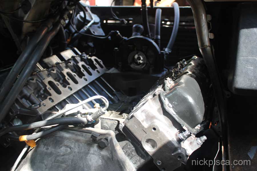
With the engine now tilted to the passenger side, there is just enough room to install the driver’s side head and the longer ARP studs. Here’s a pic of the clearance of the stud to the block:
We dangled the head like before, then pulled the crane back until I could weasel it on the head dowels. The driver’s side head had 3 studs that needed to be rubber-banded into place, but the push rods all went in after the head was seated.
As you can see the previous image if you use the furthest valve cover bolt hole and the 2nd intake bolt hole, it will allow the head to hang at a perfect 45 degree angle, almost matching the block surface slope perfectly.
On a different head gasket job on an engine stand, I have more information detailing the specifics about the head, head stud, and head gasket installation. Check it out here:
7.3 IDI Cylinder Head, Head Gasket, and ARP Stud Installation
We reinstalled the motor mounts. The passenger side mount was kinda ripped up, so I snagged a mount from the 6.9 that I scrapped out last winter. With the engine back in place, we have just enough room to slide the valve covers back on. The passenger side valve cover is freaking CLOSE to the wall.
Next we installed a new valley pan and the newly painted intake. The holes on that valley pan were gawd-awful small. Is it supposed to be that PITA? If you have never done this job, the installation of the intake and valley pan happen at the same time, becuase you need to install permatex under the valley pan, and then use the intake bolts to tighten it down. None of them lined up, and we had to really weasel them in to get them to work. It might be prudent for people to zap those holes with a drill press and bore them out a little. Not only is it a pain, but because you are on the clock (the permatex at the front and rear of the valley pan is drying) it is one of those things where you are pressed for time.
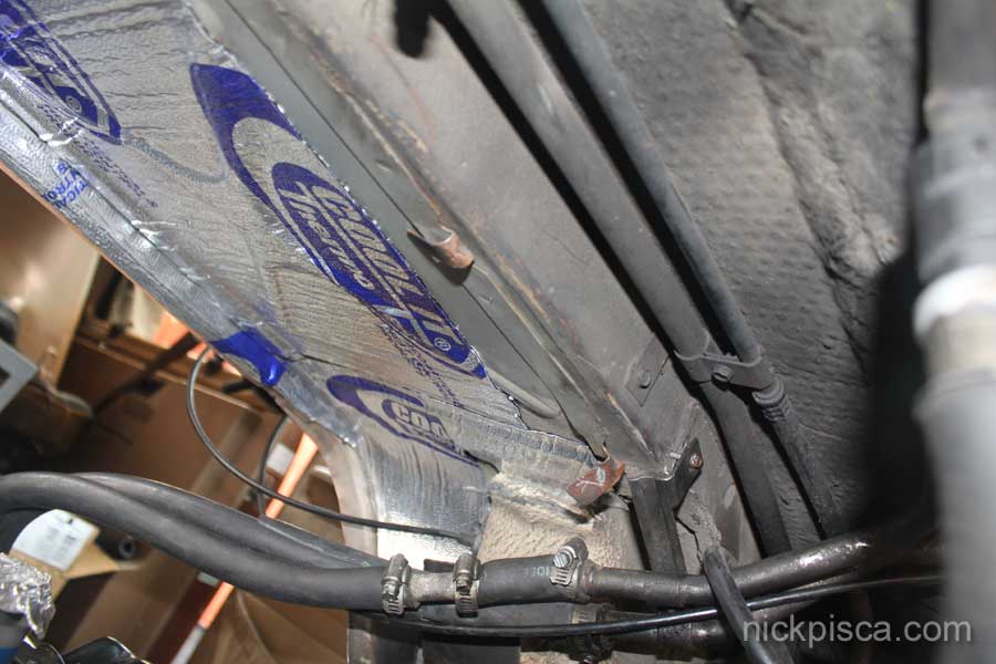
While we had the van engine wall insulation off, we installed some more sticky reflective insulation.
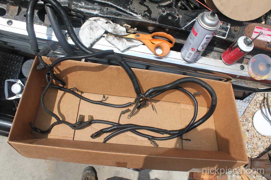
I redid the glowplug and sensor wiring harness while I had it out. Super clean now:
Reinstalled the wiring harness before we put in the IP. (you can see some of the brackets for the power steering and AC pump are reinstalled on the front of the new heads. Also the vac pump was installed at this point too)
We cleaned up the injectors, installed new caps, return hoses, and clamps (the red clamps in the image above and below).
We reinstalled the IP. To save time, I connected the injector lines before i inserted the IP. Not tight, but a little loose so that I could manipulate them as necessary. Once the IP bolts and gear bolts were reinstalled, then the lines were torqued down.
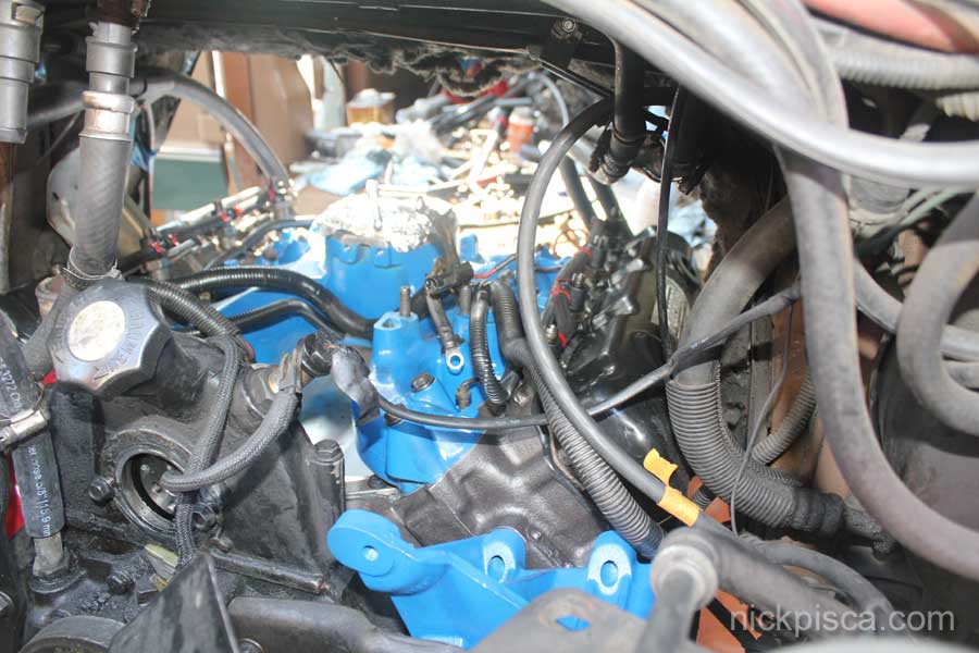
The hypermax kit comes with a glowplug relay platform (driver’s side over the 4th cylinder). It was a pain to access before because the air filter assembly blocked it from the rear and the stock diesel filter head blocked it from the front. Since I did a stock diesel filter delete on this project, I upgraded to the R&D IDI Performance Stage 1 filter system, which is mounted under the van. That affords me A LOT more room in the engine bay, which is very much welcomed. In the image below, you can see the GP relay on the right, and the 3g alt (with tach sensor) on the left. Also, since we still are trying to remove the oil in the coolant, we reinstalled the t-stat housing (painted red) without a t-stat so that we could circulated the L-11 emulsifier better.
We put the Hypermax kit back together. After putting that engine back together, we remarked on why it took us so long to install the Hypermax kit the first time a few years ago. Comparatively, it was childs play.
Non-related to this build: When I tore down the 1984 E350 6.9 last winter, it had a tranny cooler. I stowed it away and while the radiator was out, we took a few minutes to install that cooler behind the grill. Hard to see, but not only does the tranny cooler sit behind the emblem, but the former van donated its vertical supports. Sweet!
The image below shows a bunch of stuff. First off, i have two aluminum tees joined into an “H” shape. This allows for two ports and two bibs for the fuel supply. The top has a brass diesel-rated Schroeder valve at the highest point in the system. Due to the stock diesel filter delete, I need a port to bleed the air out of the system. I bought them off of ebay, and they come with a brass thread on cover. Looks pretty nice. Hope it lasts. With the diesel filter deleted, my two plugs (WIF and “Fuel Filter” sensors) were cleaned up, greased with dipole grease, and then wrapped up with plastic wire wrap and electrical tape. That way if I ever need to go back to stock, they will be protected.
Also, in the image below, you’ll see a cheapo FRAM filter. That is NOT my only filter. I have two Stage 1 R&D IDI filters under the van. That is just a temporary filter to catch any particles that might have entered the system when I put this engine and fuel system back together. It will be removed after a few days of driving.
Also, there is a Hydroforce selector valve that allows me to switch between the ford stock fuel system, and the secondary biofuel circuit.
Also, the AC pump is reinstalled and the bracket cleaned up.
In the picture below, we painted the exhaust manifolds with high-temp silicone paint, and then wrapped them with 1″ header wrap. The doghouse gets really hot, so I’m looking for anything that will reduce the temps radiated from the engine. We’ll see if it helps at all.
Another great find is the caps I found for my head studs. Those are from McMaster Carr, and we bought them on a lark. We figured it wouldn’t match the threads, but maybe we could just tap them on the stud with a mallet. But surprisingly, it matched the threads perfectly! Here’s a link to the part.
On the passenger side EM, make sure to install the oil dipstick tube simultaneously, or else it won’t fit in the engine bay. We didn’t get a new o-ring, so we used permatex.
We cleaned up the parts, and scrubbed the carpet with cleaner to get rid of all the oil ground into the fabric.
We reinstalled the seats, started her up and she ran. She’s running pretty nice. I marked the rotation of the IP in the hopes that the timing would match the pre-HG-job orientation. The engine sounds pretty good. The only oddball thing is it is burning some black smoke at moderate to high R’s. I’m still waiting for a timing gun and ferret meter to check the timing, but if the timing is good, i’ll just turn the fuel screw down a flat. Not sure why the fuel would increase after replacing the IP, but my theory is that my new filter assembly is a likely cause. The stock diesel filter assembly had a pin-hole bib that would allow excess pressure from the lift-pump to cycle back to the tank. I don’t have that with my new setup. The e-pump pushes thru the stage 1 filters then to the IP, without any bleeder line, so that means all the pre-IP fuel pressure is affecting my timing or fuel supply.
Timing and Performance:
I timed the engine today. Straight after the HG job, it was running at 8 deg BTDC. Not bad, and actually that is pretty much what would be OK for running this aftermarket turbo. However, the engine is still blowing a lot of black smoke, so something was off.
I tuned it back to 4.5 deg BTDC, like in my previous thread on FTE: https://www.ford-trucks.com/forums/1…direction.html
It ran and sounded almost exactly like the engine previous to the HG job. So that was good. I did a lot of MPG and performance testing last year, and hopefully that same timing will afford me the same performance. But, it still billowed a lot of black smoke when I gave it even a moderate amount of accelerator.
I turned the fuel screw down a complete flat. Odd really, cuz I figured after doing the HG’s, i would be turning up the fuel to really spool up the turbo.
The engine only produced a small amount of black smoke at WOT, so I think this is good. I took it on the highway to see the turbo results.
Flats at 60mph: 2-3psi.
Up gradual hills at 70mph: 4-7.1psi
I never exceeded half throttle, and I didn’t get to try out a hill yet. But those numbers are pretty awesome considering my previous performance. I should be seeing over 10psi up some decent hills or pulling some weight.
My EGT’s never exceeded 750 deg F either. My duramax high-flow exhaust is letting the temps egress quickly.
If you haven’t seen my timing video, here’s the link:
I originally put the turbo on to save MPG. however, i can’t help myself from gunning it at every stop light, on ramp, passing situation, etc. And cruising at 75 mph with LA traffic is amazing. Somehow, someway, I NEED to figure out how to keep it at 55mph…. someday.
Updates:
After 2 years, the heads and studs had held up well. The HG job didn’t fix the oil-in-coolant issue. After ten thousand miles of driving, I finally pulled the engine to find a new block. Eventually, I moved the heads and studs to a ’94 IDI block. I’ve been told you can reuse ARP studs up to 3 times before they suffer some fatigue. When I removed the heads, they showed little wear and the precups looked decent. So as far as I can tell, things are still working well. I fired it up with the heads on the ’94 block and the seals and gasket seem to be in great performance condition.
No warranty. You are responsible for your vehicle. For novelty use only. Not responsible for anything or anyone. Not responsible for damage to your vehicle, you, or anyone or anything.
Copyright 2000-2018 Nick Pisca 0001D LLC