Ever since I bought my 1988 IDI Van, I’ve always had some weird electrical gremlin regarding my headlights. Out of the blue, the headlights would shut off randomly. It happened so often, that I installed very bright auxiliary headlights for the times I was driving at night and my headlights randomly shut off. My elders, who have upgraded their lives to have cars with wi-fi and touchscreen dashboards btw, would talk about back in the ol’ days, a faulty headlight system likely pointed to a malfunctioning footpedal high-beam switch. Heeding their advice, I replaced the foot pedal switch, because they are prone to failure from all the snow, water, and mud that gets tracked in on the floors from everyday use. The movement of the high-beam switch to the steering column was a marked improvement for cars in the 1980’s, but my van is a dinosaur with which I refuse to modify.
So, after three different foot-pedal high-beam switch replacements, I finally determined, that the foot-pedal wasn’t the problem. Something else had to be the culprit.
So I pulled out the old Ford Service Manual to see the wiring diagrams. Sadly, no help there.
After checking all the grounds, I figure the headlight switch itself was the problem.
I bought a new motorcraft headlight dimmer switch (Motorcraft SW6352 Headlight Switch) assembly and removed the leftside dash panel to get an idea of the situation. Prior to working on my van, I pulled the battery cables off the terminals, so that I don’t accidentally short any wiring out when I’m working on it.

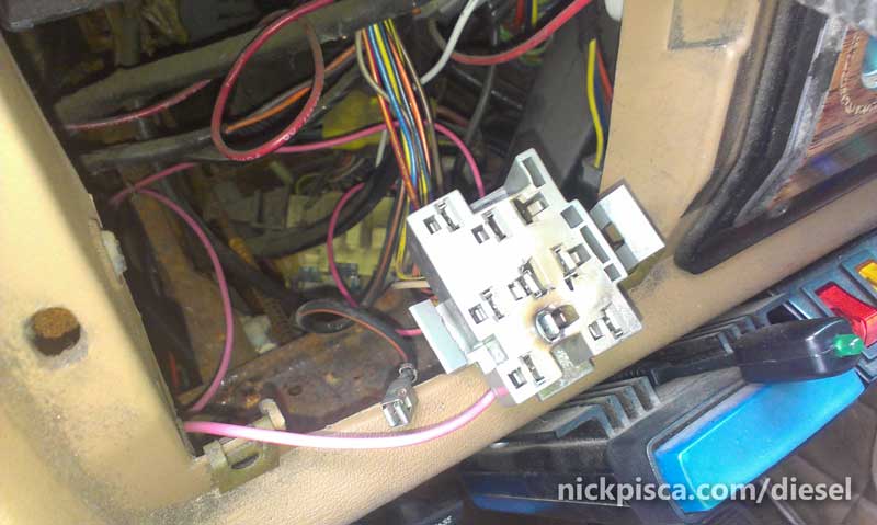
When you pull the panel away, the Ford engineers have fortunately given enough wiring to move the panel far enough to see inside. The headlight switch is a large metal and plastic assembly at the bottom. At first glance, my headlight switch looked ok. No real visible issues or burn marks. Since mine was 30 years old, I figured it wouldn’t hurt to replace it even if this didn’t resolve my headlight issue.
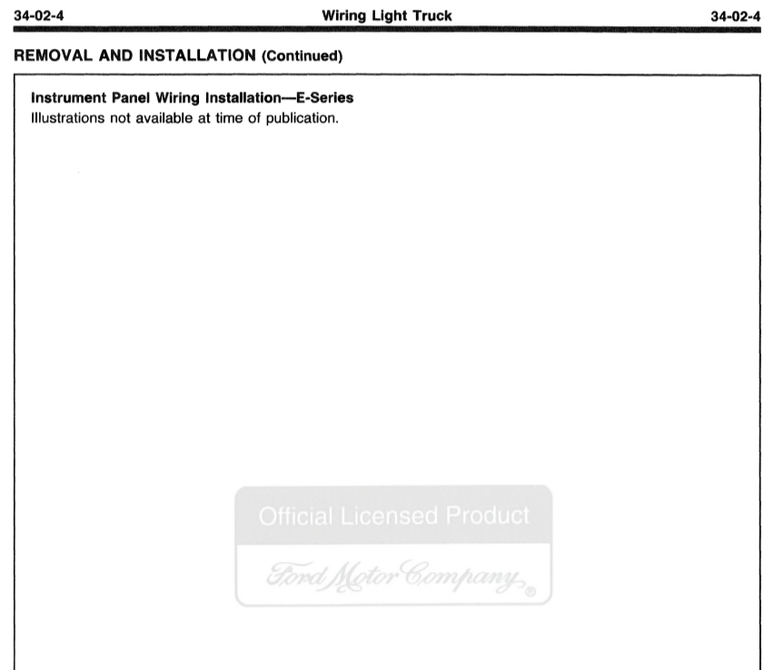
In order to disconnect the switch from the dash panel, you need to remove the nob. There is a release button on the inside that allows you to extract the nob. Press it and then pull the nob straight out.
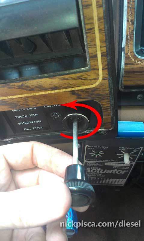
From the front of the switch panel, pull the nob out and turn the plastic bushing counter-clockwise to unscrew it. Do NOT unscrew the nob. UNSCREW the black colored bushing next to the “LIGHTS” word pictured below:
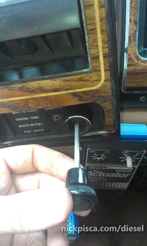
Once disconnected to the dash panel, undo the grey electrical connector from the back of the switch assy. At first glance, my pigtail looked ok.
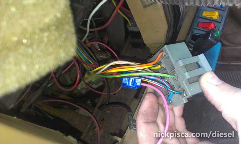
As you can see, I have a pink wire that connects to the light relay for my aftermarket gauges to dim at night. However, that has never worked properly. My gauges, even though they are wired correctly, never dimmed at night like they are supposed to. I just put up with it, but it would have been nice to have them the proper illumination especially on dark long rides thru the night.
However, as I looked at the face of the pigtail, the problem became evidently clear.
Several of my connectors have burned or even completely fallen out. I’m still astonished that somehow it completed the circuit for the headlights. The black-and-red wire, which feeds the headlight power supply, was totally disconnected to the circuit. Very odd.
Anticipating this, I had previously purchased a Standard Motor Products HP3820 Headlight Dimmer Switch Connector pigtail, just in case I had this larger electrical issue.

Amazon Images
If you have to replace your connector, make sure to buy good quality butt splices and preferably heat shrink your wires for longevity. Also, do not expect the wire colors to match. The new wire might not be the exact same color; instead, when you cut off the old connector, look at the location in the back of the connector and match that to the old wire, instead of just matching colors.
Sadly and anticlimactically, I forgot to take a picture of the final heat-shrunk new connector in place. It isn’t that sexy, just a bunch of wires. But would be nice to see the progress. I was able to remove that slider-connector for my aftermarket gauges, and splice it into a heat-shrunk butt-splice so it looks really pro.
Remember, with any electrical fix, whenever you reconnect the battery terminals, be sure to have an ABC fire extinguisher just in case you wired it improperly. Promptly after reconnecting the battery terminals, watch and smell for burning plastic. If you wait too long, your whole dash could be on fire because that old plastic can burn very easily.
And after all of it was reconnected, my gauge dimming worked at last! Reinstallation is the reverse of the disassembly. If you are having electrical light issues, maybe this article could help you.
Improved Wiring Strategy:
On the FTE IDI forum, some IDI veterans have redesigned their systems to employ dedicated relays to improve the wiring system. Ford designers pushed a lot of current through this wiring harness, and ideally, the lights should be executed via a relay to reduce the power requirement. FTE User “cadunkle” posted a great picture and description of his headlight relay setup here: https://www.ford-trucks.com/forums/1479713-headlight-woes-2.html#post17023554
He writes: “See if you have room to mount a RTRM panel anywhere, either inner fender or on the fender itself. I’m glad I went all out and did it nicely. It only took an evening after work to get the box wires up and a Saturday to install and make up the wiring, most of which was figuring out where to mount it, moving other crap out of the way, cleaning up PO messes, and figuring how to run the wiring to be neat and tidy.
I used this one: 15303-2-2-4 It’s only 4.5″x3.5″x4.5″ LxWxD installed with brackets.”
He posted this photo of his setup:

No warranty. You are responsible for your vehicle. For novelty use only. Not responsible for anything or anyone. Not responsible for damage to your vehicle, you, or anyone or anything.
Copyright 2000-2018 Nick Pisca 0001D LLC